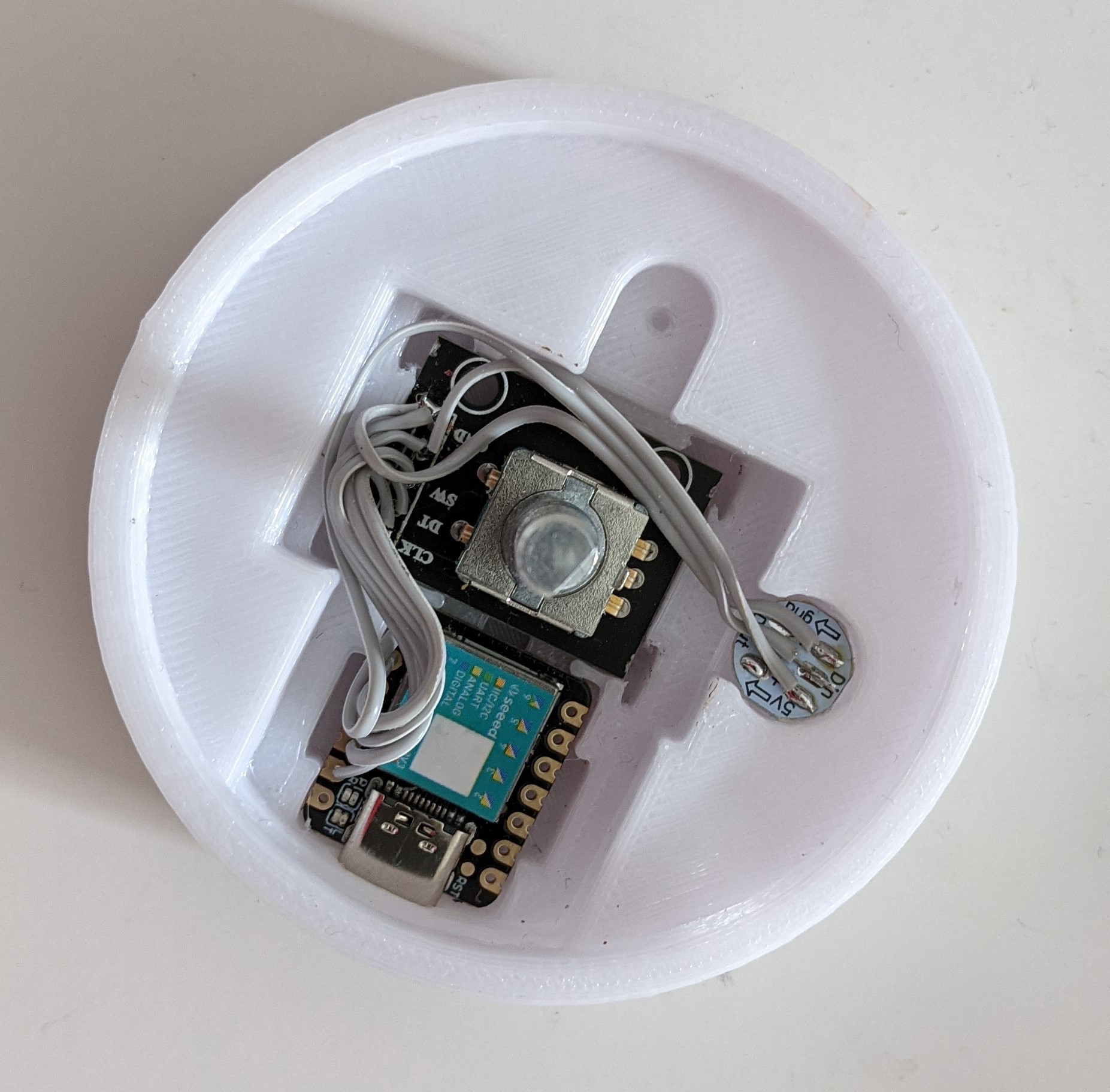
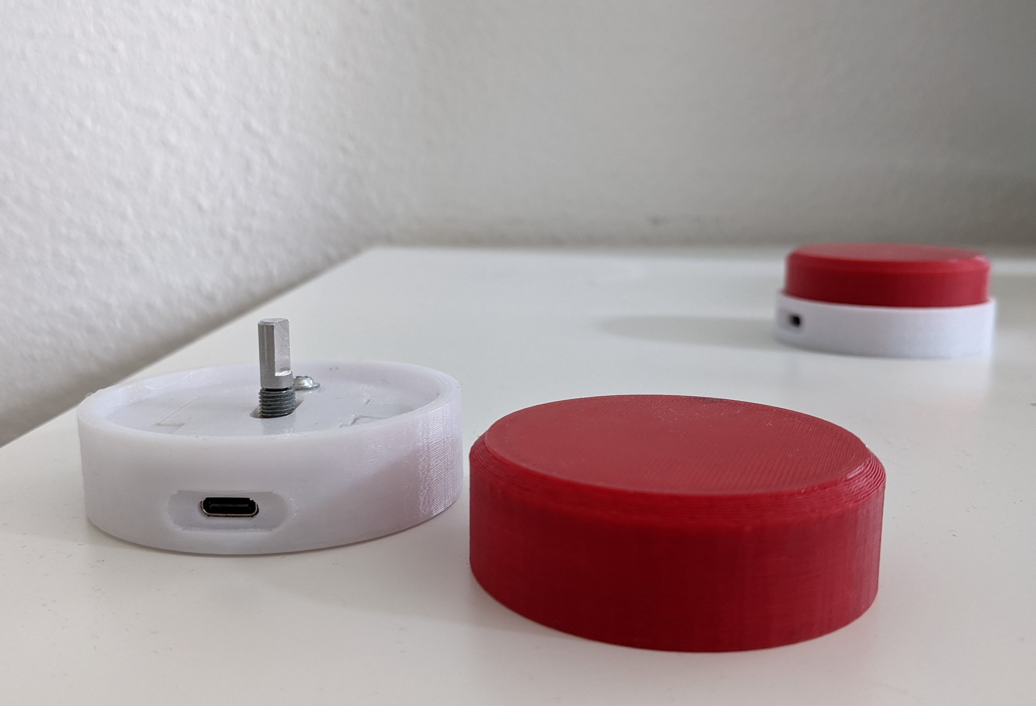
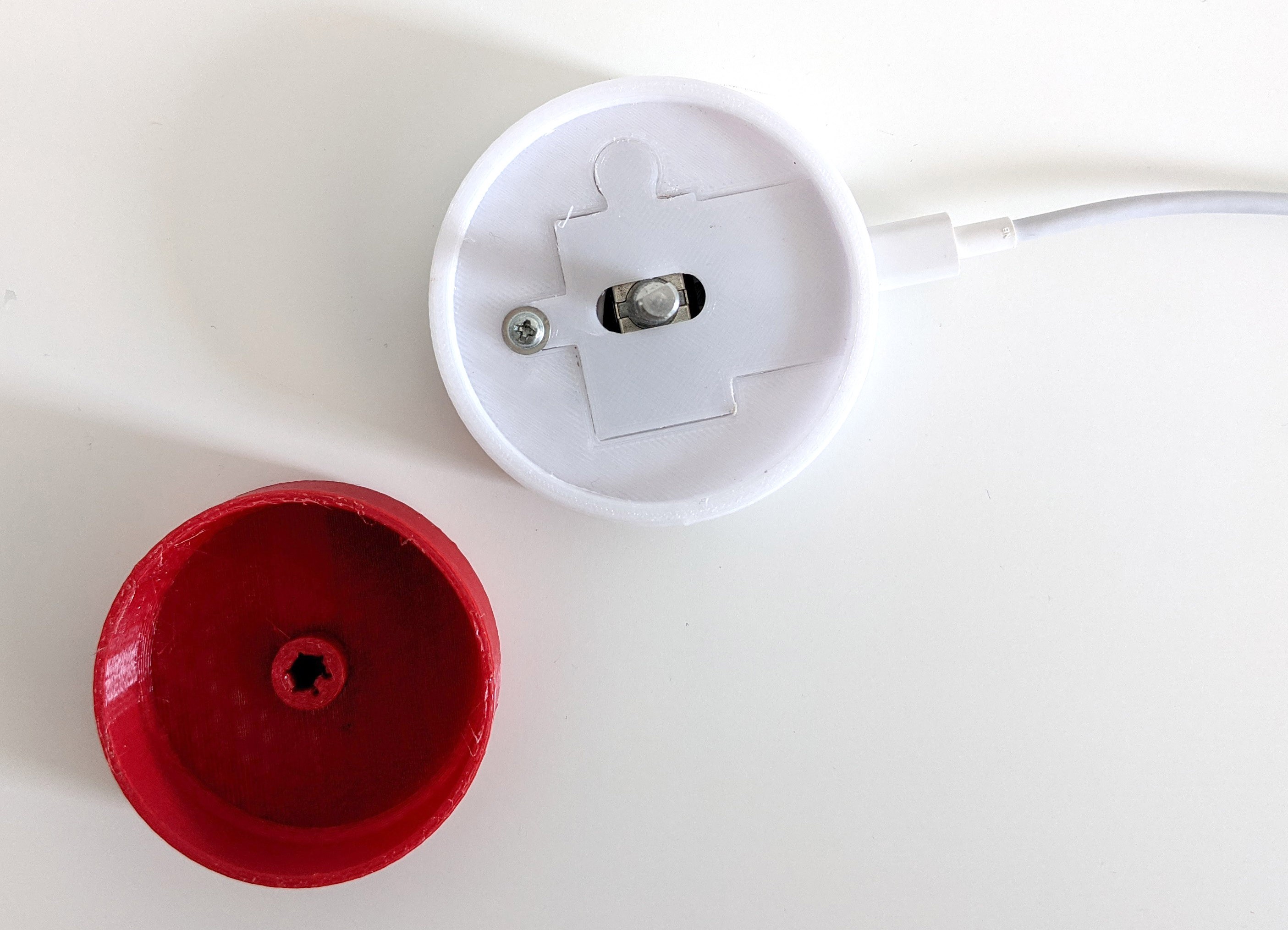
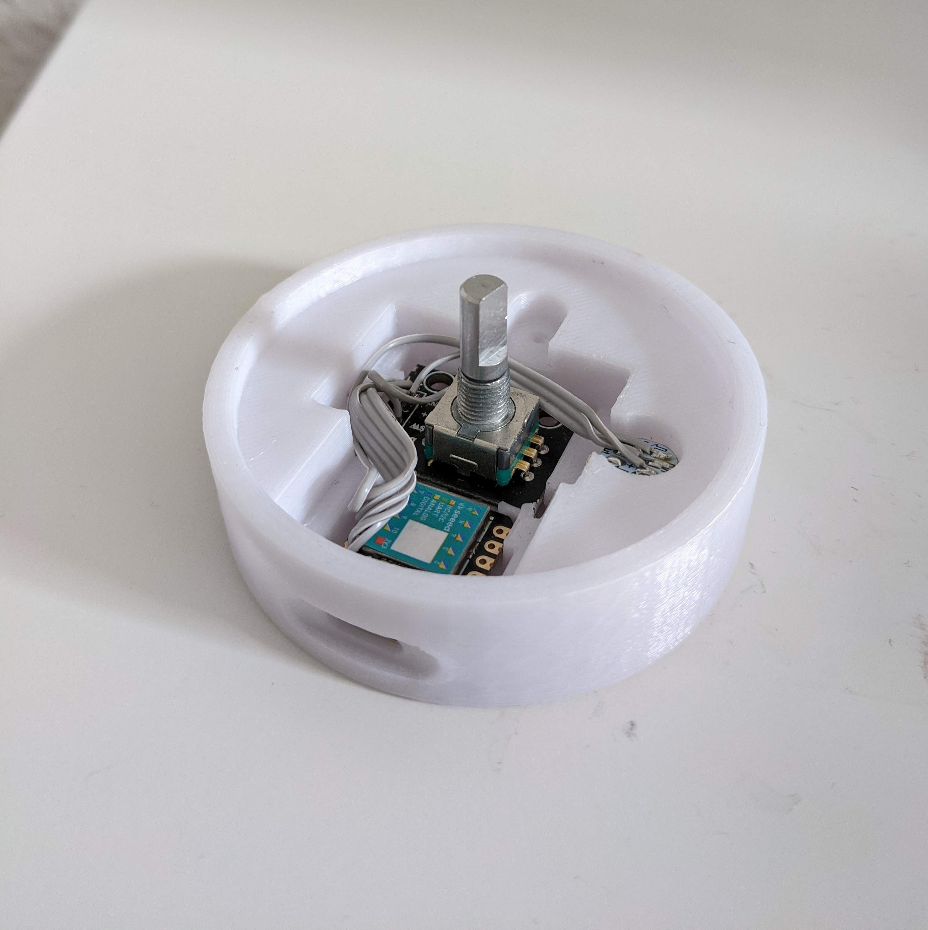
In a first step, Myute is assembled without any PCB. Wires are soldered between the Seeeduino Xiao, the KY-040 and the WS2812B RGB LED. The base and wheel are both designed with FreeCAD and printed with PETG.
Arduino is used to read the KY-040 by including the following lib: https://github.com/dmachard/KY040-rotary
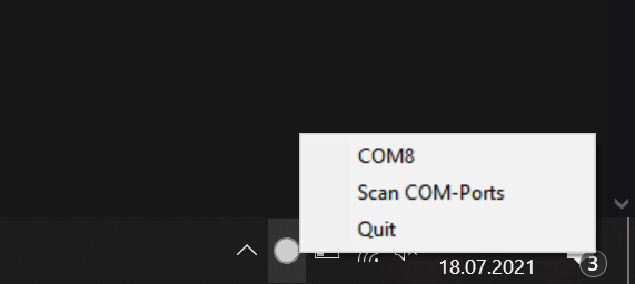
A C++ Application is developed with Visual Studio to let any Windows Compute interact with Myute.
The following features are implemented:
- right / left turns decrease / increase the volume
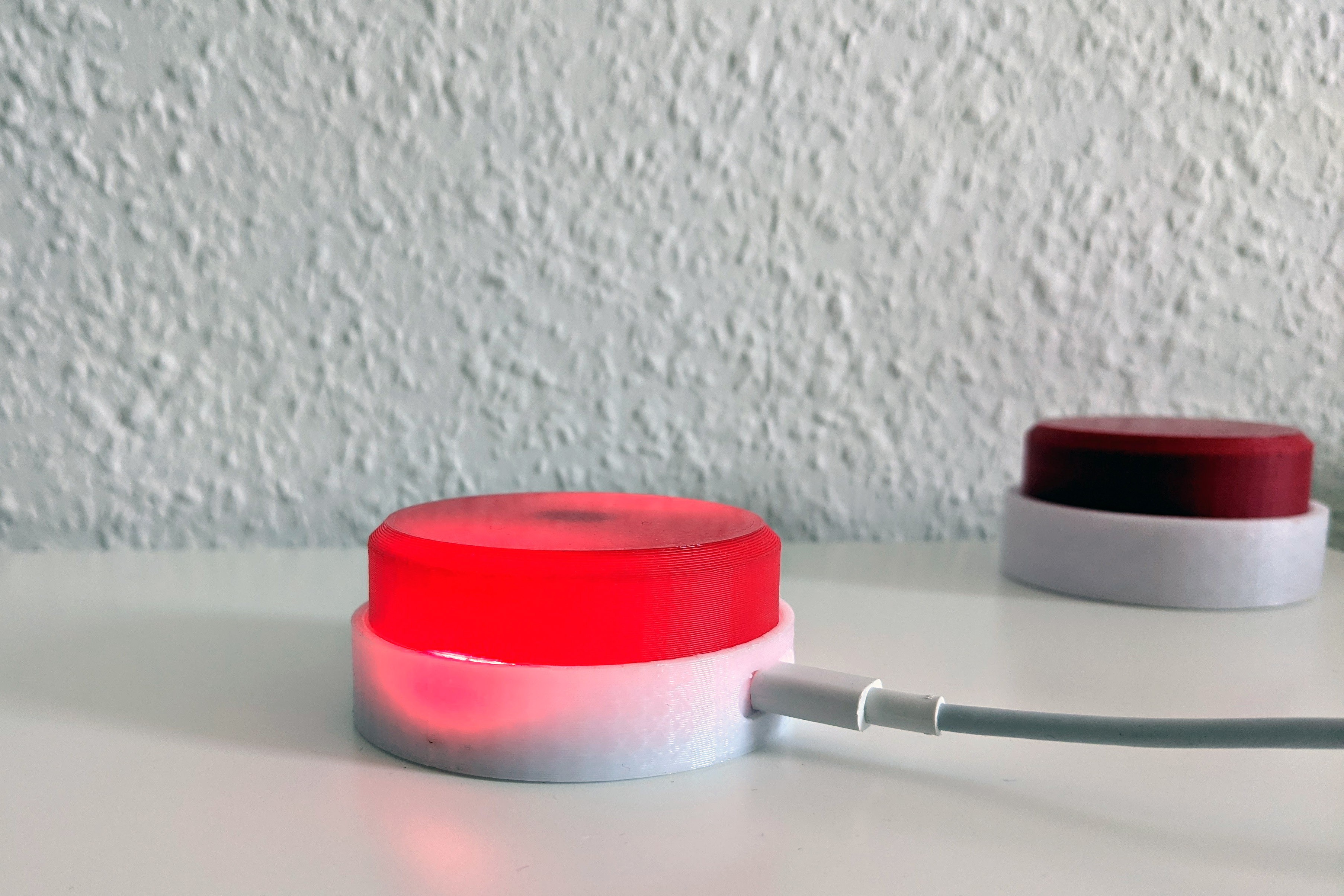
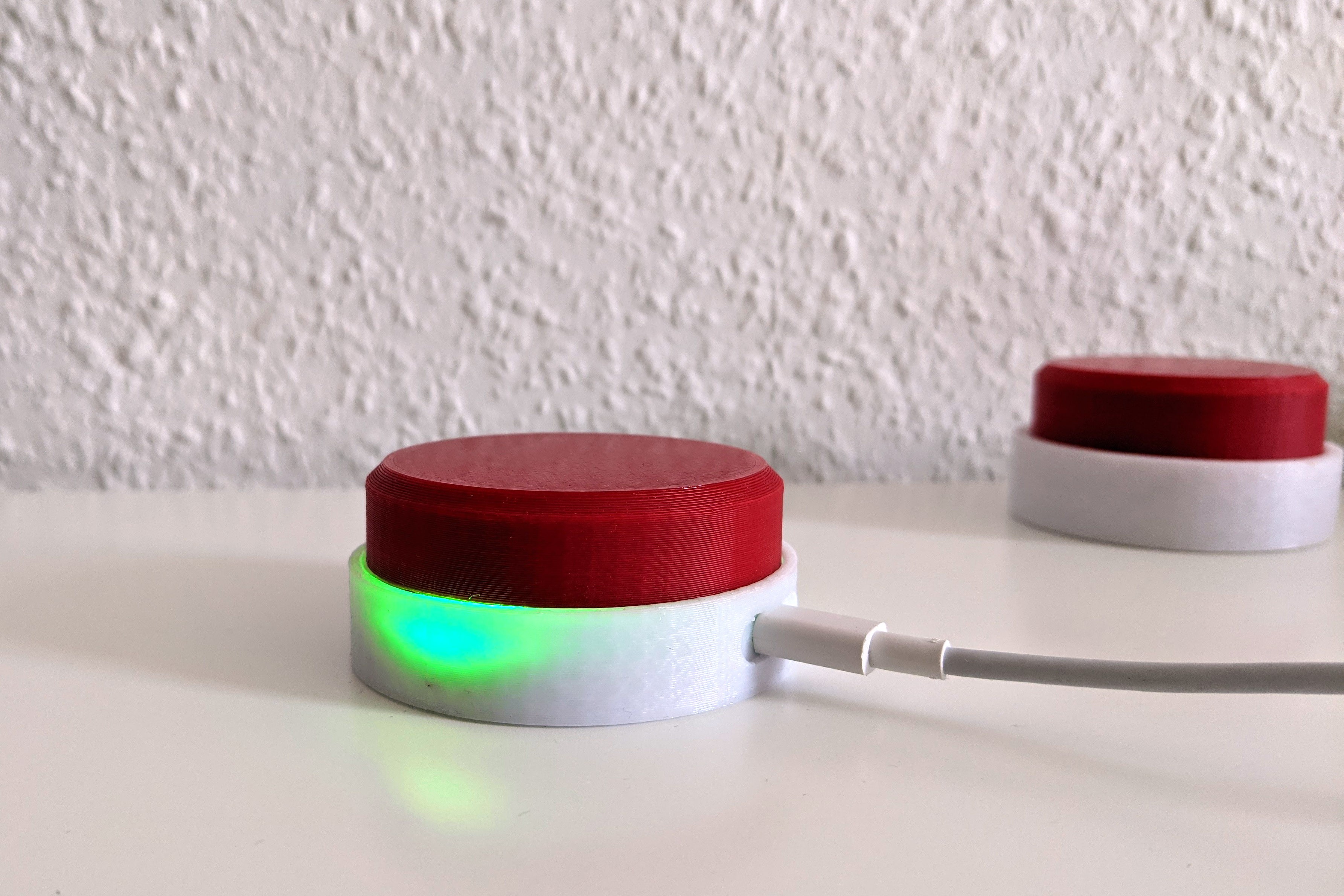
- a button press either mutes or unmutes the microphone
- the RGB LED indicates the current mute status
The C++ Application is scanning COM-Ports at startup. If avaiable, it automatically connects to the Myute Hardware.
Discussions
Become a Hackaday.io Member
Create an account to leave a comment. Already have an account? Log In.