 Thomas
The Inspiration for the M1 came from thinking about the difference between polar and cartesian coordinate systems and how they are applied to real world machines.
Cartesian Coordinates:
Cartesian coordinates are relatively intuitive both conceptually and from an application standpoint, any point in the plane is defined by 2 discrete coordinates on the X and Y axis.
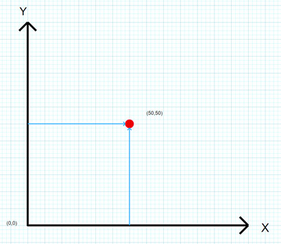
In application cartesian machines are super simple. If you want to move say a drill or pen to a point X = 50mm, Y = 50mm from a known origin all the machine needs to do is move 50mm along the X and Y axis.
For more info about cartesian machines this is a great starting place.
https://www.youtube.com/watch?v=XYqx5wg4oLU&ab_channel=DIYMachines
Polar Coordinates:
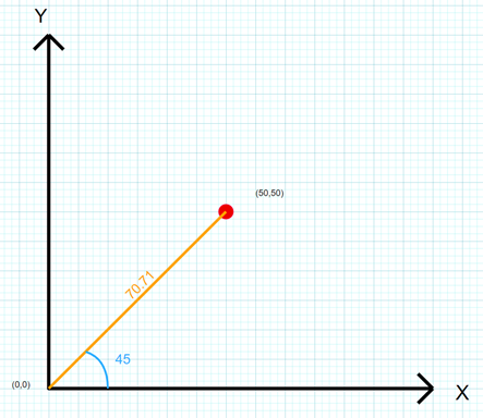
Where cartesian co-ordinates define a position on a plane using X and Y points, polar coordinates utilize angle and distance to define position.
In terms of application machines that utilise polar coordinates strictly in terms of angle and distance are not very common. This is primarily for 2 reasons.
- High precision of the encoder required to measure the angle (I’ll talk about this in a later log)
- Polar machines are essentially very long levers which means even a very small force at the end of the arm requires a very large counteracting torque at the point of rotation.
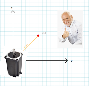
In summary a purely polar machine would need a massive, very accurate motor……. Not an easy combination.
But what if we could remove one of these two requirements? What if we remove the motor and instead move the arm by hand while we measure the angle. We could accurately go to any point simply by setting the distance and rotating the arm until it was perfectly aligned with the point. Easy right?
Not exactly. Though setting the distance is easy with something simple such as a belt drive. Very precisely positioning the arm angularly is another matter, even a very small angular misalignment of 0.1° means we will miss the target by a significant margin. This misalignment also gets worse the longer the arm gets.
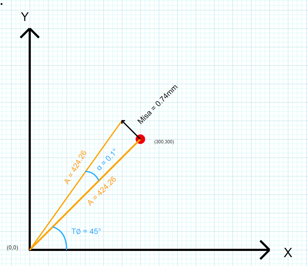

For example if we were trying to position the arm over the point X = 300, Y = 300 in Cartesian coordinates we would need to rotate the arm to exactly 45°. But if we were off by even 0.1° (45.1°) that would mean an absolute misalignment of 0.74mm..... not cool.
The Solution:
To solve the misalignment problem I am going to add an axis (B axis) perpendicular to the A axis that can move slightly back and forth. With this small amount of additional play in the B axis we will be able to compensate for any angular misalignment.


The exact details of the mechanism and inverse kinematics will be detailed in a later log.
A small demo of how exactly the M1 tracks position is below
Even when the whole device is rotated the carriage maintains position over the target point.
Discussions
Become a Hackaday.io Member
Create an account to leave a comment. Already have an account? Log In.