 Tim
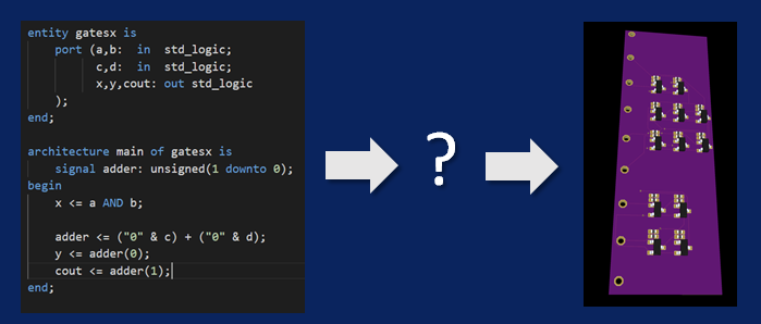
TimAs stated in the introduction, the goal of this project is to create a workflow to generate a PCB with discrete (transistor based) logic from a hardware description language file. This should happen in a reproducible and automated way, with as little user interaction as possible.
Let's get one thing out of the way first, the inevitable question of "why"? Some possible reasons:
- I'd like to use this as an opportunity to tinker with open source electronic design automation (EDA) flows and learn more about their inner workings.
- The availability of low cost PCB manufacturing and assembly services had the side effect of allowing manufacturing of complicated discrete logic circuits for little money. Nothing more satisfying than to get actual hardware from your design.
- More and more open source EDA tools are becoming available, providing a solid foundation to build on.
- Because I (possibly) can! Well...
To be a bit more specific about the goals:
- The source language should be VHDL, because that is what I am used to. Verilog is a close second, in case there is no other choice.
- The target logic family should be resistor transistor logic (RTL). The reason for that is that the MMBT3904, a bipolar NPN transistor, is currently the cheapest transistor at the JLCPCB assembly service. I may also look into NMOS logic.
- As a first step, the main goal should be to get a functional circuit that implements the HDL input. It is acceptable to compromise on performance. For example, timing analysis, clock tree insertion and power routing can all be introduced or optimized at a later time.
Discussions
Become a Hackaday.io Member
Create an account to leave a comment. Already have an account? Log In.