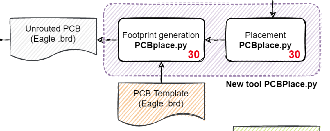
After having figuring out where the cells are supposed to go, we need to figure out how to turn them into actual components on a PCB and write them out in a format that can be interpreted by a PCB design tool. As always, I spent most of the time looking for "shortcuts" and only started implementation then.
Initially I considered using the scripting capability of Eagle or Kicad, but this turned out to be quite a hazzle. Luckily I was pointed to the great Eagle file format in a discussion on µc.net. The Eagle .brd format is well structured and free from esoteric metadata - it is a pure XML format.
It turns out that it is extremely easy to handle the Eagle format using the lxml Python package.
    def loadeagle(self,filename):
        """Load eagle file """
        self.dom = et.parse(filename)
        self.n_eagle = self.dom.getroot()
        if self.n_eagle.tag != "eagle":
            raise Exception('Invalid tag name for root node - no eagle file?')
These lines read and parse an entire eagle .brd file to the element tree structure where it can be modified at will. Saving is also just a few lines.
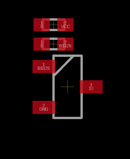
Adding components is as simple as adding XML elements. The example below adds a transistor footprint
self.n_board = self.n_eagle.find('drawing').find('board')
n_elements = self.n_board.find('elements')
et.SubElement(n_elements, 'element', name = "Q"+cellname, library="RTL_components", package="SOT23", value="PMBT2369", x=str(x+1.65), y=str(y+1.4))
After this success it was quite clear how to proceed: The script reads a template, adds the required components and saves the board to a new file. The template consists of an empty board, design rules and a component/footprint library.

At this point, all unit cells are hardcoded in a Python class. Coming up with a flexible library format would add a lot of complexity at this point, especially since only very few cells have to be supported.
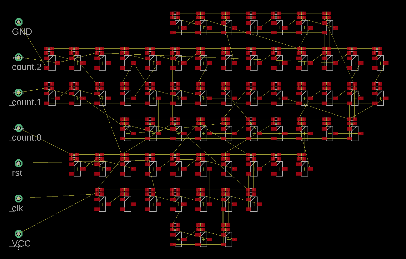
In addition to placing logic cells, also pins for the I/Os are placed on the grid.
The completed placement for the counter.vhd example is shown below. The connections are shown as airwires.

 Tim
Tim
Discussions
Become a Hackaday.io Member
Create an account to leave a comment. Already have an account? Log In.