 Malte
Malte-
1Instruction overview
To assist you in making your own Speak4Me glasses, we have provided a list of necessary steps. Since we know how challenging written instructions can be, we have also created How-To videos in which we show the steps. The steps are divided into the following parts:
Hardware Setup
2. Soldering and cutting the resistances
3. Trimming the AUX connector
4. Making the AUX connector fit
5. Soldering the AUX connector
6. Soldering the USB connector
7. Soldering the connection for the internal speaker
8. Soldering the transistor for the keep alive circuit
9. Cutting the leftovers of the transistor for the keep alive circuit
10. Placing the Arduino and EMIC
11. Soldering the Arduino and EMIC
12. Cutting the leftovers of the Arduino and EMIC
13. Soldering and cutting the leftovers of the LEDGlass setup
14. Remove the USB-cable insulation
15. Marking the connections
16. Preparing the sensors
17. Mounting the sensorsHow to use the Profile Customization
18. How to customize your profiles
19. How to customize the settings
20. How to use the upload and download functionalitiesLoad the software on your Arduino
21. Load the pre-configured code to the Arduino
Advices on how to use the glass
22. Practical advice's to use your Speak4Me glass
-
2Soldering and cutting the resistances
To start with the assembly of the necessary hardware, prepare a solid workplace and have the following tools ready to use:
- Pliers
- Rubber band
- Wire stripper
- Voltmeter
- Nail file
- Sandpaper
- Soldering iron
- Solder wire
- A helping hand or something to fix it
You will also need the circuit board and most of the components you had to order before.
In case you never soldered something before, we highly recommend that you first familiarize yourself with the process by asking a hardware-addicted friend or starting with one of the various tutorials to be found on youtube and solder a few things to get familiar with the process. You will not need any advanced soldering skills for this project, tho, so everyone should be able to perform the soldering steps on his own in a manageable amount of time. Once you feel confident, get back to the board and start soldering.
Start by consecutively positioning the resistors, fasten them using the rubber band and then solder them to the board. Afterwards, cut off the protruding legs of the resistors.
The whole pcb assembly process has been documented in the following video (Click here to go to the first step of the video.):
-
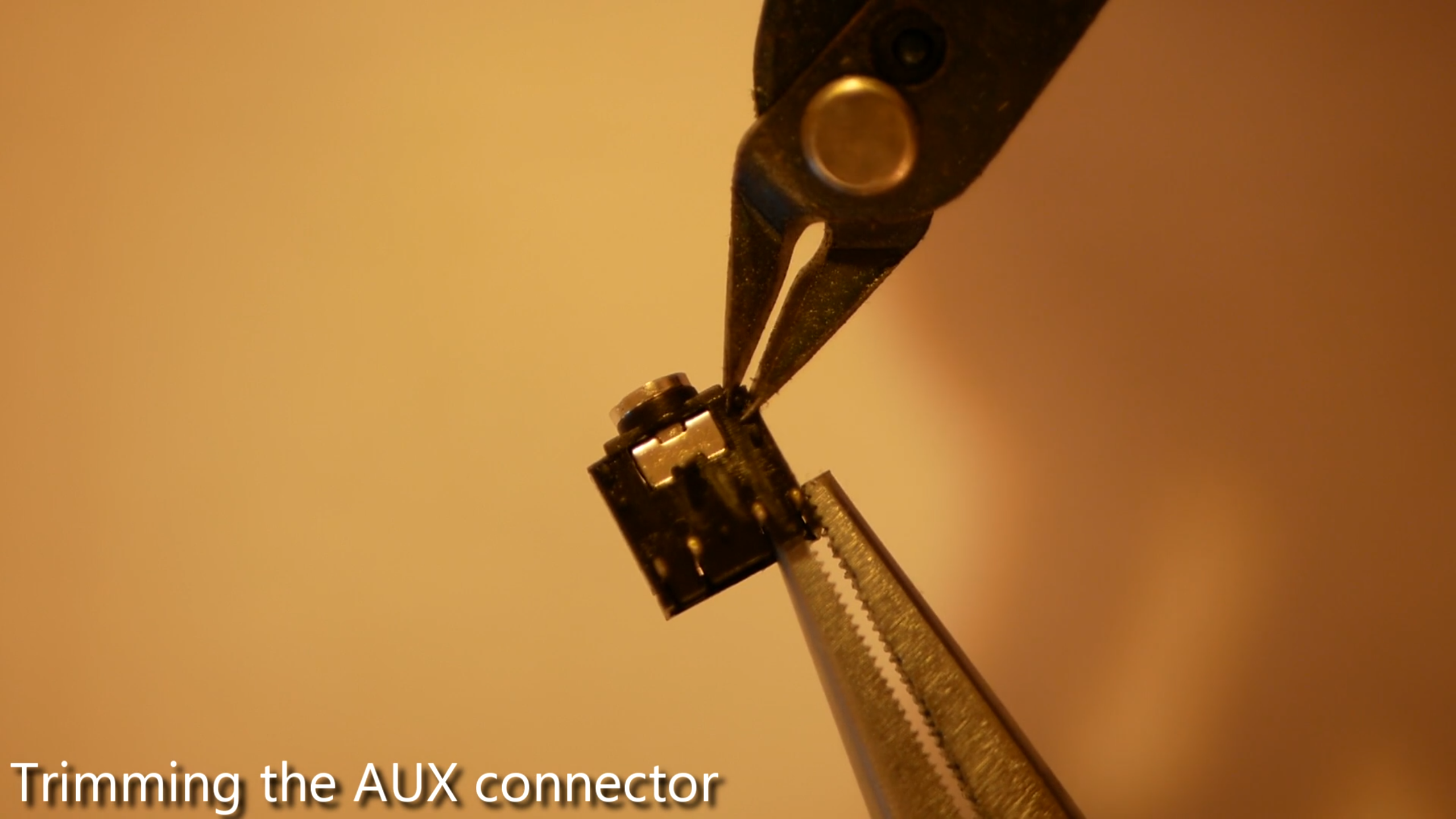
3Trimming the AUX connector
Most aux connectors have small brackets on their bottom side, which shall help to keep the connector in place. We do not need them, so please just clip them off using your pliers for example.
![]()
-
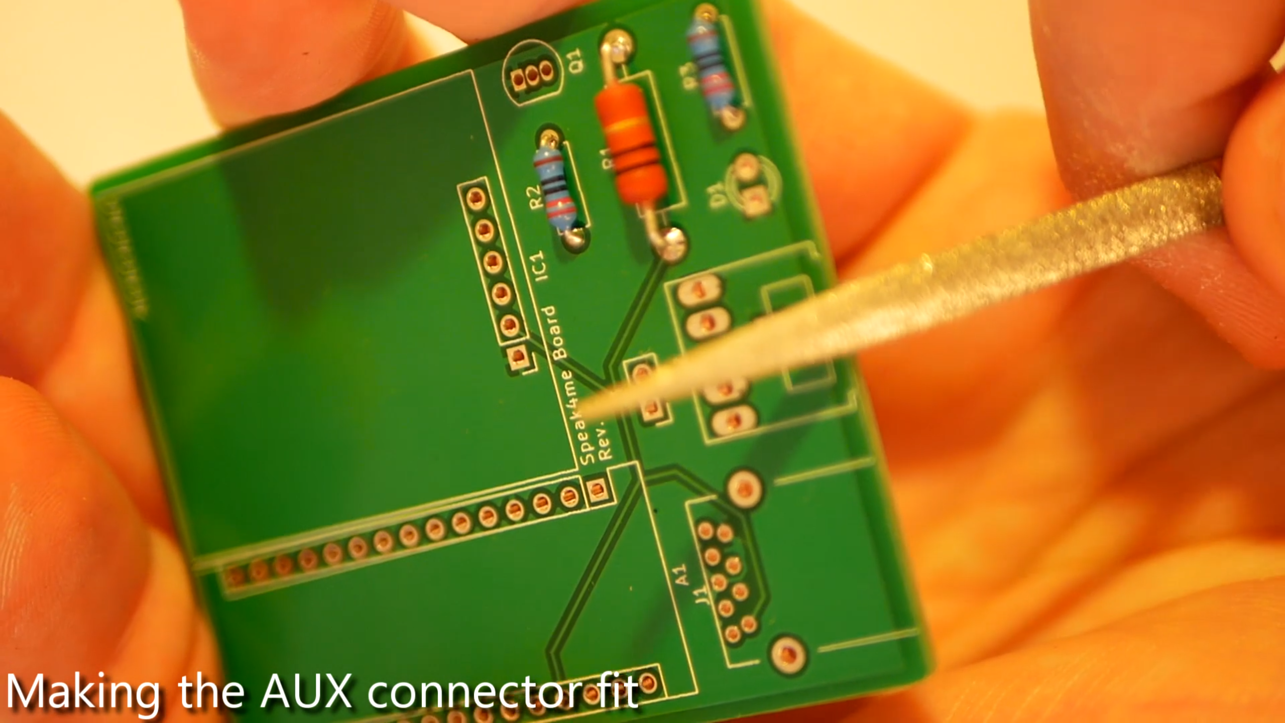
4Making the AUX connector fit
In order for the aux connector to fit on the pcb, file off a small piece of it. You're done when the connector rests neatly on the board and no longer tilts.
![]()
-
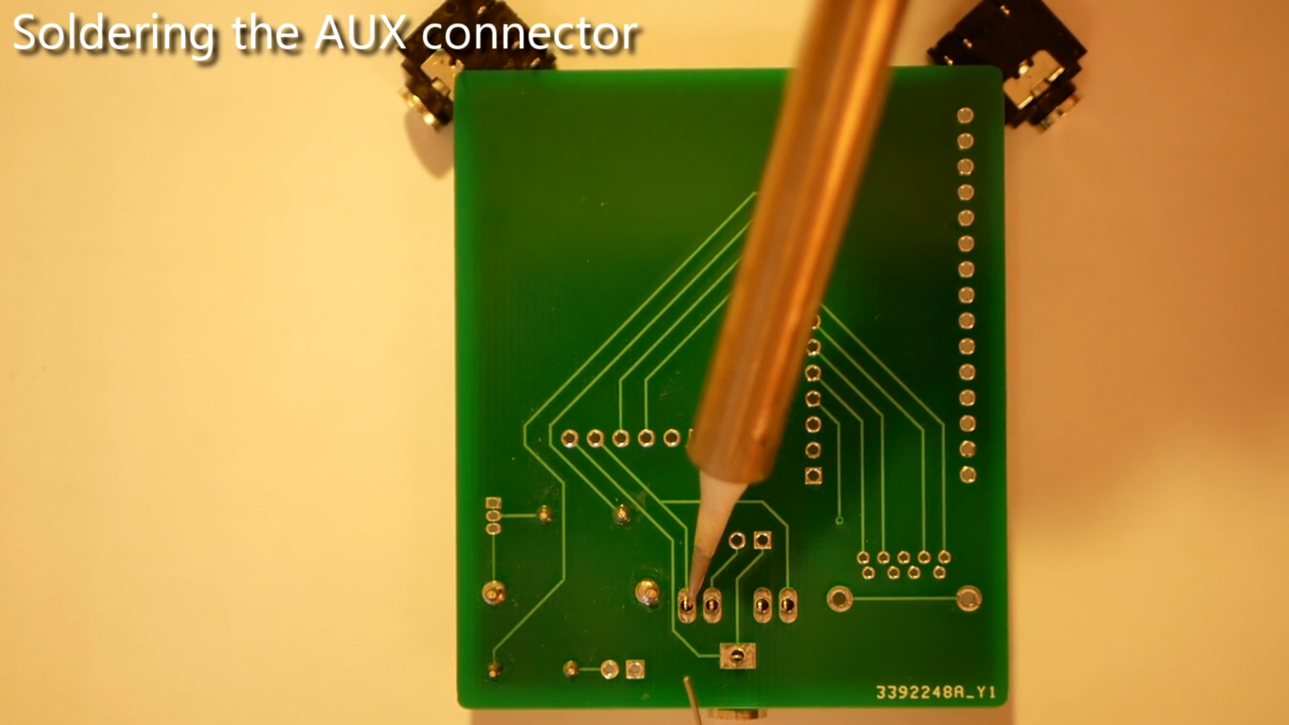
5Soldering the AUX connector
Put the aux connector in its place, make sure its sitting tightly on the board, fasten it using the rubber band for example (in the video, we simply used remaining connectors to stabilize the pcb) and then solder it to the board.
![]()
-
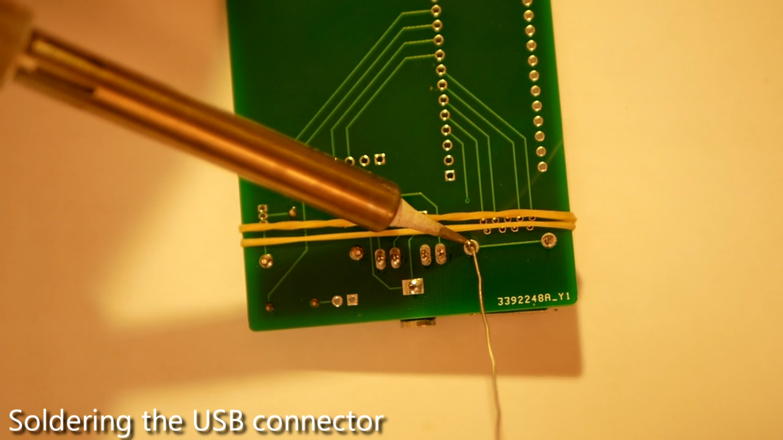
6Soldering the USB connector
Next, put the usb connector in its place and fasten it by using the rubber band, again. We recommend to start by soldering the two bigger pins and then removing the rubber band. Afterwards, be very careful when soldering the remaining little pins. If you accidently connect several pins, it might be necessary to get a desoldering pump (a cheap one for a few dollars is completly sufficient). Then, desolder the affected pins. If you are unsure if two pins are connected, use a voltmeter to check. Be aware that a connection between the wrong pins can result in a short circuit and might damage the pcb, the arduino or even the pc connected to the device.
![]()
-
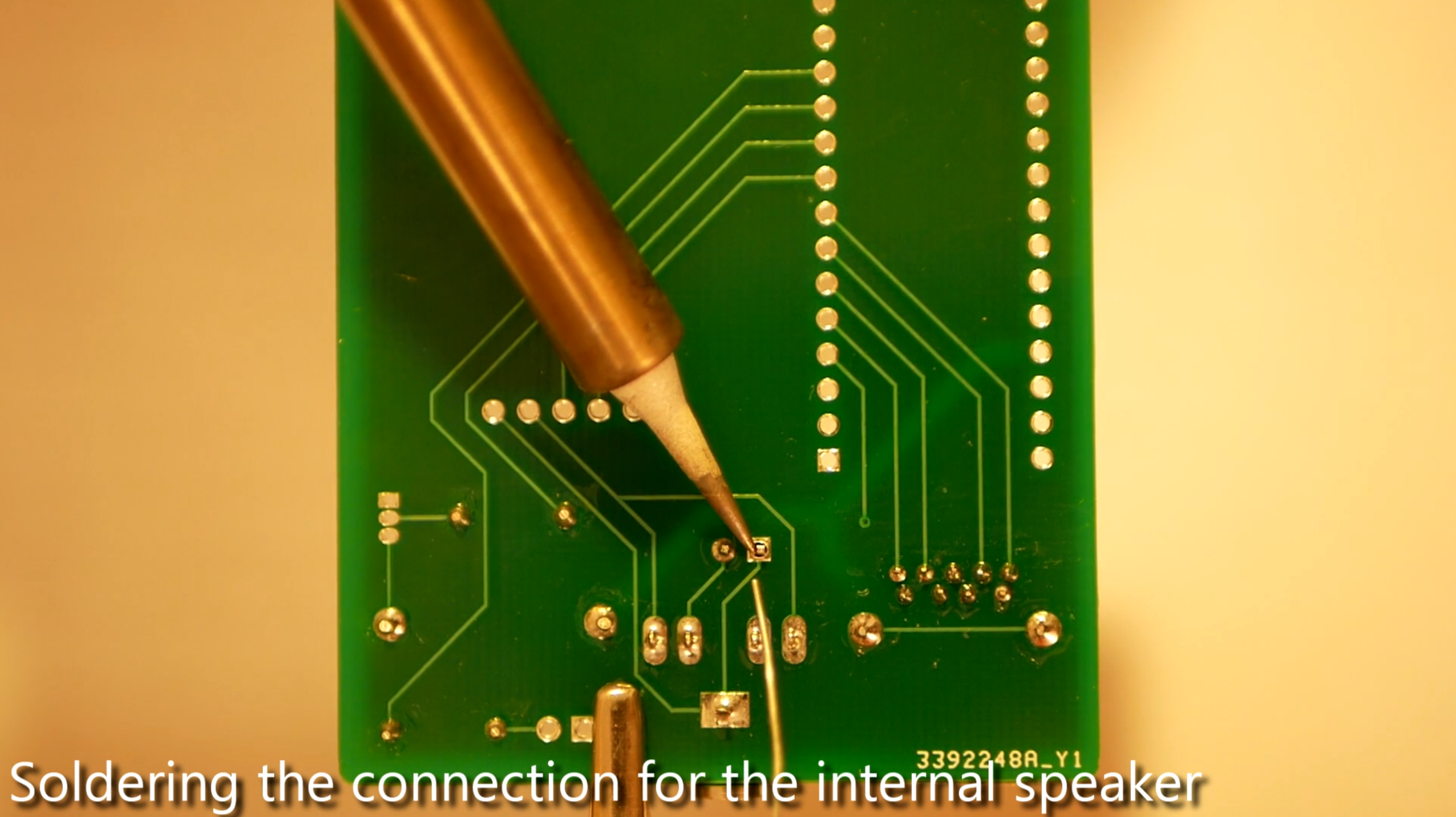
7Soldering the connection for the internal speaker
In this step you have to solder the connection for the internal speaker.
This step is optional if you plan to use an external speaker via the AUX port only.
Click here to go to the corresponding part of our video.
-
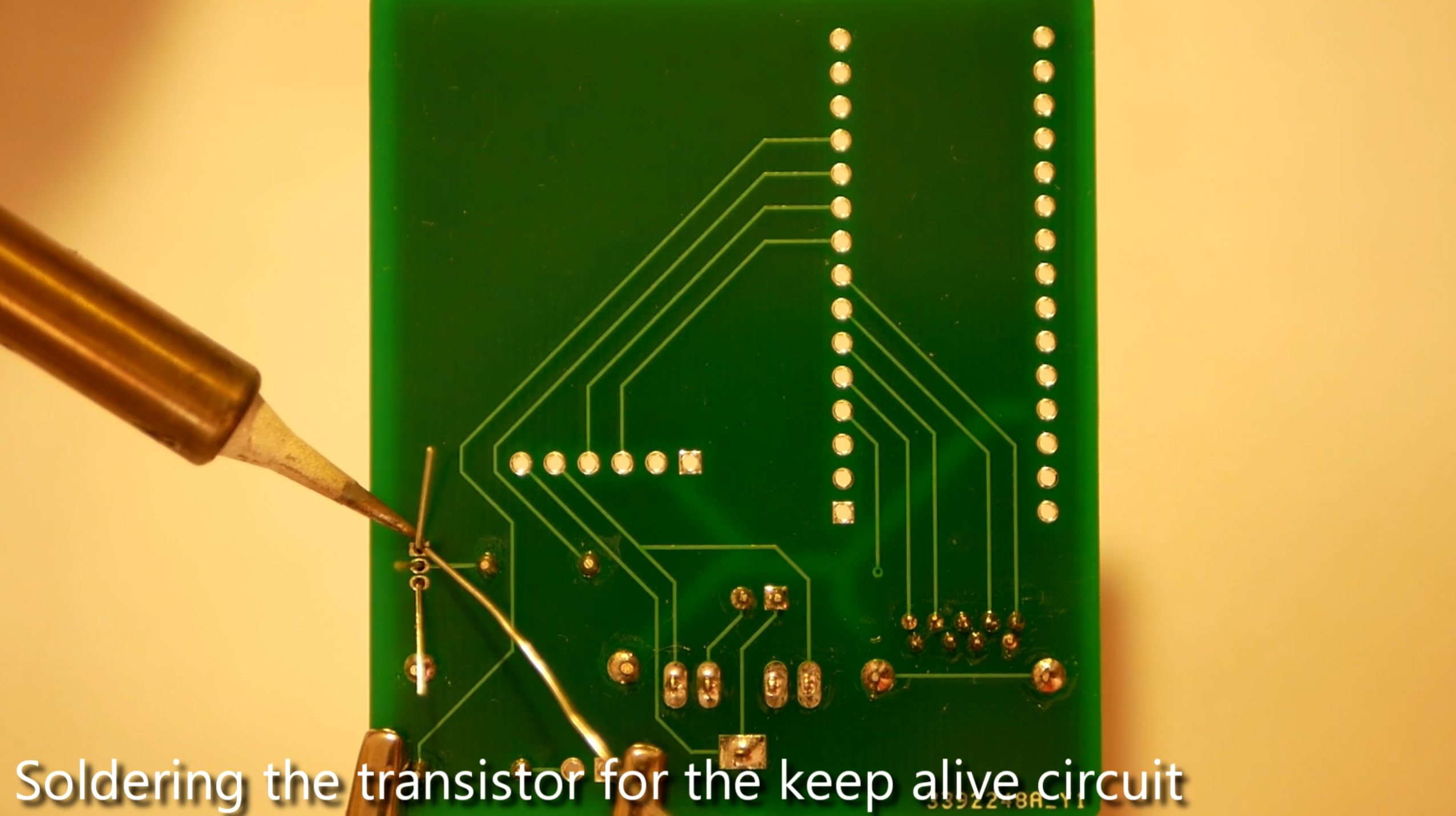
8Soldering the transistor for the keep alive circuit
In this step you have to solder the transistor for the keep alive circuit. The keep alive circuit is necessary because some powerbanks stop charging when not enough power is consumed.
-
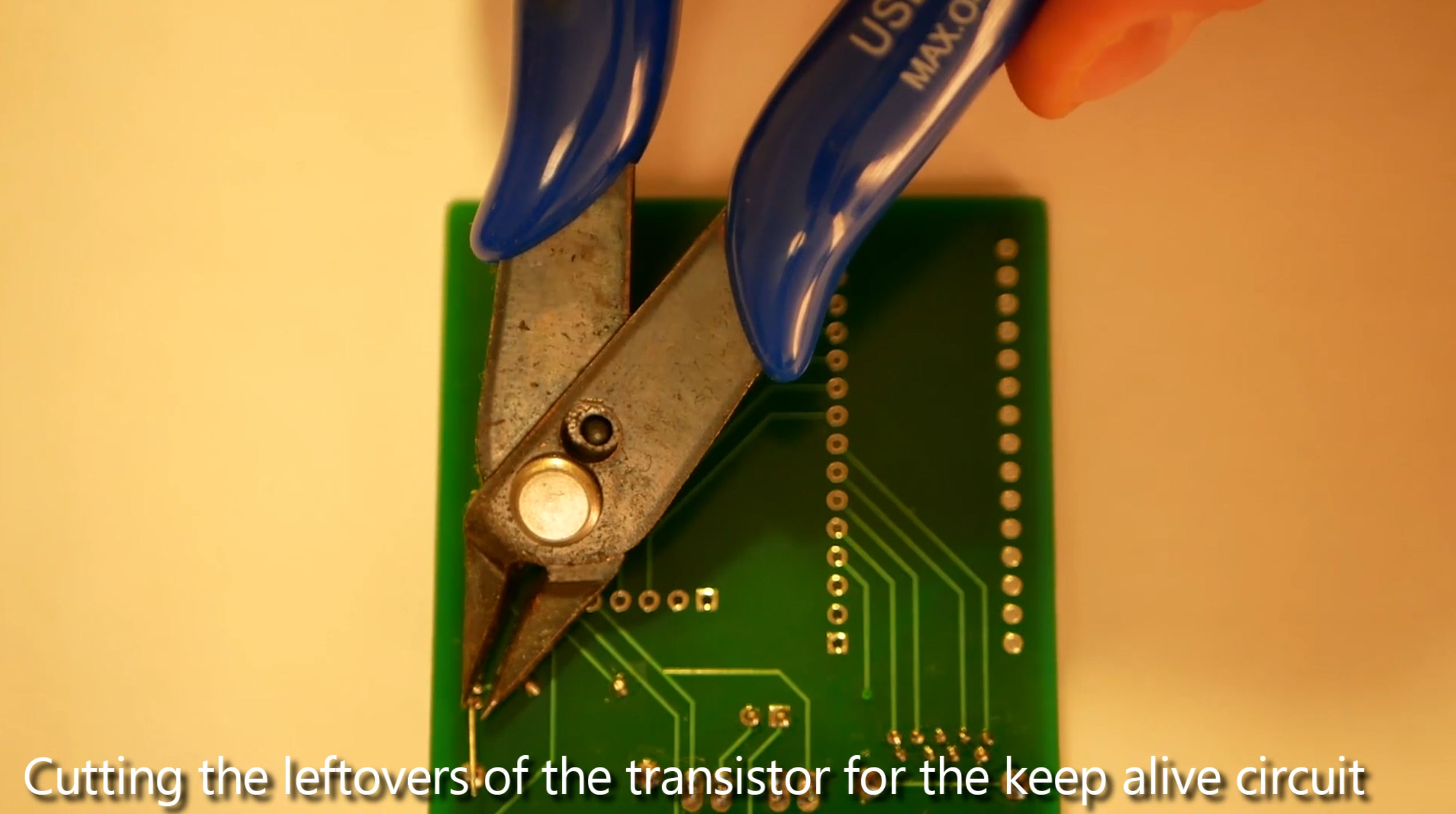
9Cutting the leftovers of the transistor for the keep alive circuit
Here you have to cut the leftovers of the transistor of the keep alive circuit you have just soldered. For this purpose a simple pair of pliers is enough.
-
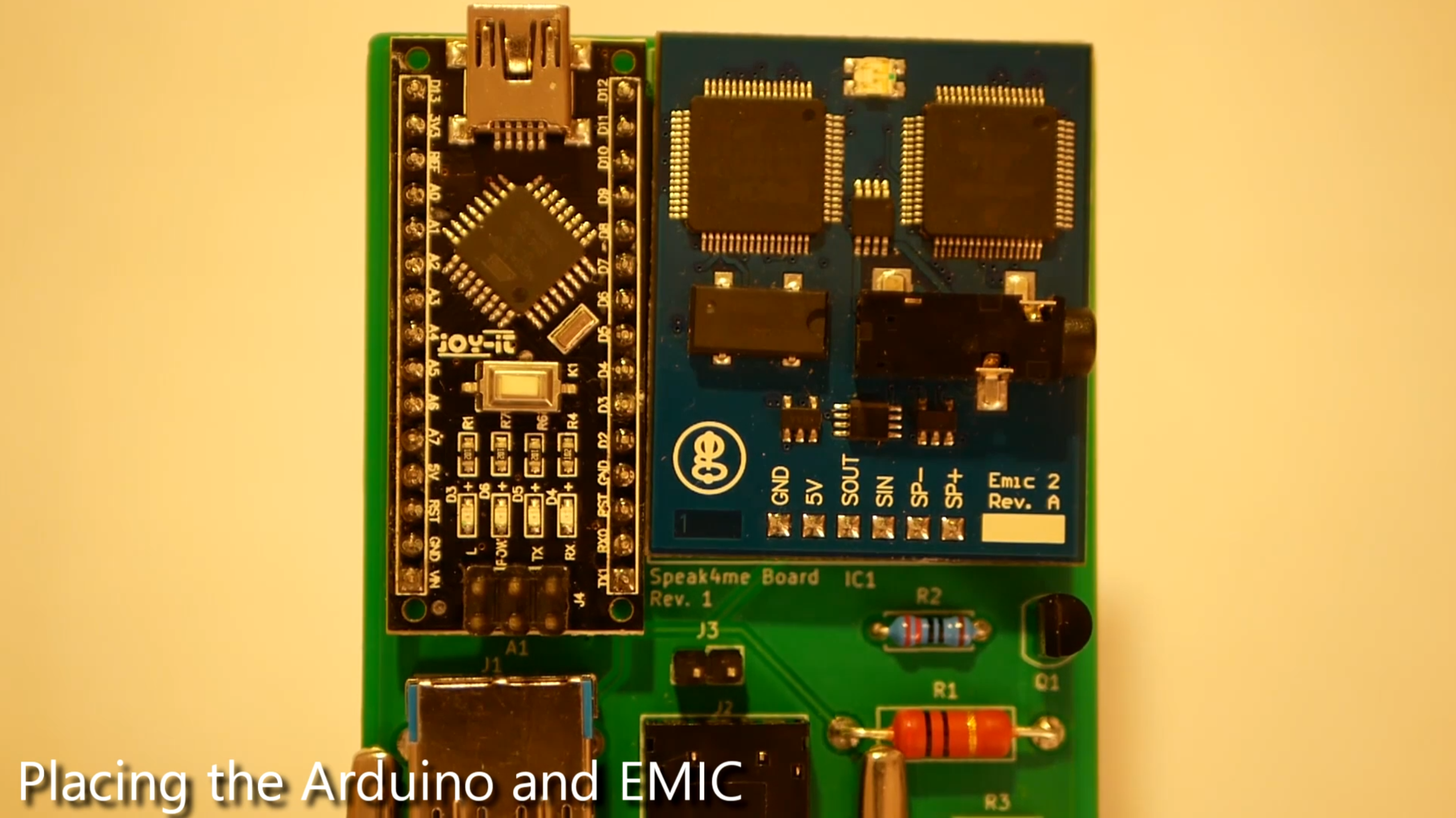
10Placing the Arduino and EMIC
In this step you have to place the Arduino and the EMIC on the board. Make sure to place the two parts gently and then fix them with a rubber band.
Eye-to-Speech Module
We want to help people who are unable to communicate verbally and cannot use sign language by providing a wearable “eye-to-speech" solution.
Discussions
Become a Hackaday.io Member
Create an account to leave a comment. Already have an account? Log In.
Wow, well put together! I'm going to coach some kids into finding people to build this for, and building it.
Are you sure? yes | no