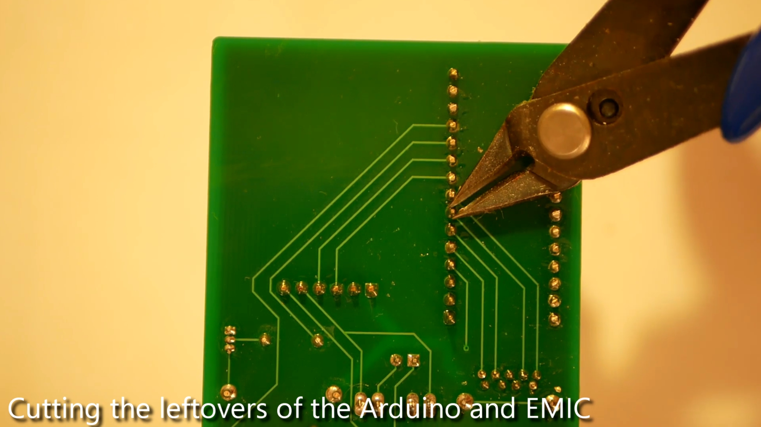
In the last step of the Hardware Setup, solder the LED to the circuit board and cut the leftovers of the soldering process.
14
Remove the USB-cable insulation
To start with building the glasses, the insolation of the USB cable needs to be removed. Start with the dismantling of the cable by carefully slitting the insulation of the cable, for example with a knife or a scissor. The exact structure of the cable might vary depending on its quality, but they should be very similar. After you slitted enough, you can simply pull the outer insulation (the thick plastic) to remove it. Untight the next laxer of insulation (thin plastic) with you fingers and remove it by cutting. Remove the next layer of insulation (aluminium foil). Be careful that you do not damage the thin cables. Additional layers of plastic foil can usually be removed by patiently twisting the wires until the foil starts to disconnect from them. If ground wires for the signal return or marker yarn exist, remove them.
Now, the connections need to be marked. Start by skinning the first wire. If you are using a Voltmeter, you can for example use the diode test mode. Any other method, which reliably detects a connection between two points works as well. By this, you need to make sure, which of the wires corresponds to which USB Pin on the other end of the cable (Red is for example usually current and black is usually ground). Mark Pin 2 (the Left sensor), Pin 3 (the Upper sensor), Pin 4 (The Right sensor) and Pin 5 (the lower sensor) with different coloured insulating tape. After verifying and marking all connections, put a shrink hose over the wires, which will later be used to tightly connect the cable to the glasses.
As the next step, you should prepare the sensors. Since we do not need the mounting holes, simply cut them of every sensor with a wire cutter to save some space and sand the cuts with some sandpaper. Cut the wires of every sensor to a proper length, skin them and twist them. Power and ground must be twisted with a second wire, which will lead to the next sensor, but the data pins should be twisted as well. Tin-coat them, insert each wire into the according hole of the according sensor, solder the wires to the sensors and cut of distant wire ends.
Try the positioning (since you cannot move the cable afterwards anymore) and shrink the cable. Mount the sensors onto the 3D printed plastic mount and connect the sensor mount with the glasses. Use for example some high-quality double-faced adhesive tape for these steps.
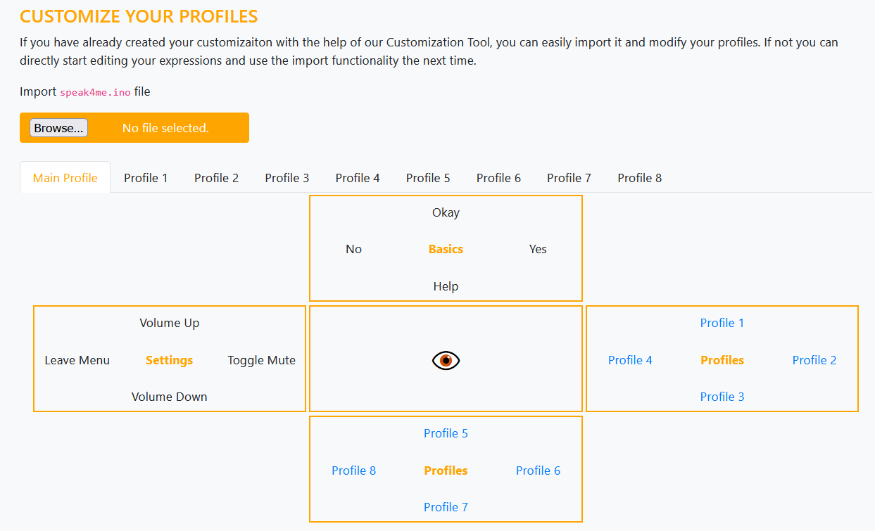
To make setup easier for people without coding experience we have developed a no-code customization tool. You can easily use the tool on our website in the browser. Either use the navigation button on the homepage to get to the tool or use this direct link.
If you already have a configuration, you can upload it to the tool so you can continue working on your configuration.
If you put the glasses on and look up twice, "Okay" will be displayed. If you look to the right and then up, you switch to profile 1, where your configured commands are available.
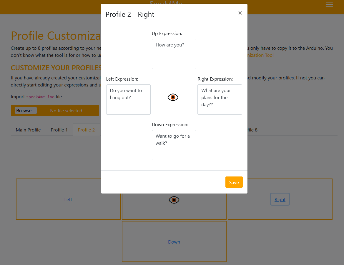
For configuration, select a profile in the graphic or with the help. Then click on the position and enter your expression in the popup.
The explained instructions are shown in the following video from 0:00 to 1:03
19
How to customize the settings
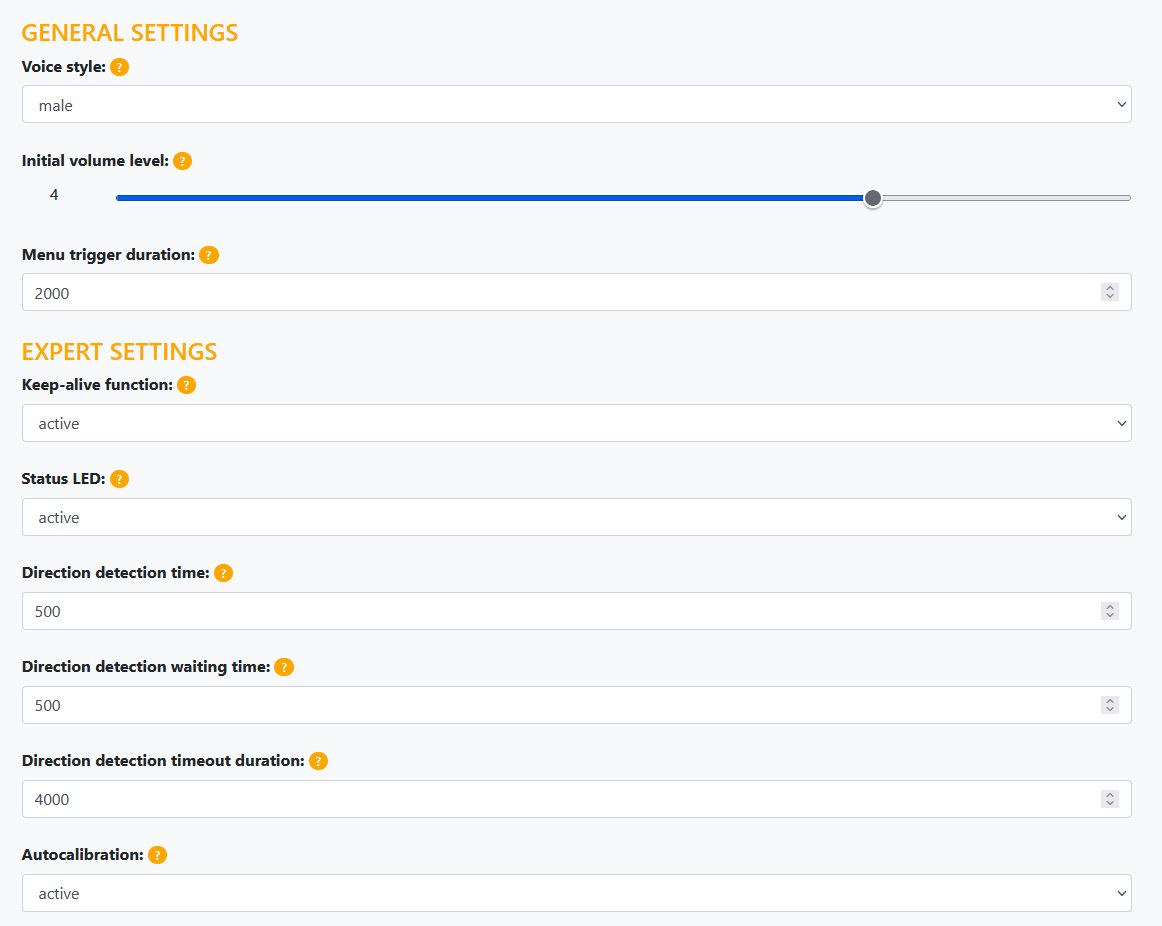
After you have set up the profiles, you can continue setting them up further down the page. For example, you can set the voice and the initial volume. If you need more specific settings, this is possible under "Expert Settings". If the individual setting options are unclear in their effects, you can find out more information by clicking on the organic question mark. During the development we have gained some experience and have set these values as default in the configuration. So you don't have to change anything, just see how you get along with our values and change it if needed.
Starting at 1:03, it is presented in the video below.
20
How to use the upload and download functionalities
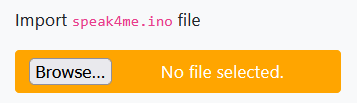
If you are satisfied with your configuration (profiles & settings), you can download the coding for the Arduino simply by clicking on the button "Download your profiles". After that you only have to copy the .ino file to the Arduino and the clock can be used with your configurations (explained in the next chapter).
To learn the configuration better, there is also the possibility to download a PDF with your configurations using the button "Download profiles as PDF". This will surely help you to know at the beginning, on which combination, which terms are.
If you want to change your configuration later, just use the upload function in the customizing tool. This will upload your profiles and settings back into the tool and you can edit them again and finally download and use the glasses with the changes.
Starting at 1:32, it is presented in the video below.
 Malte
Malte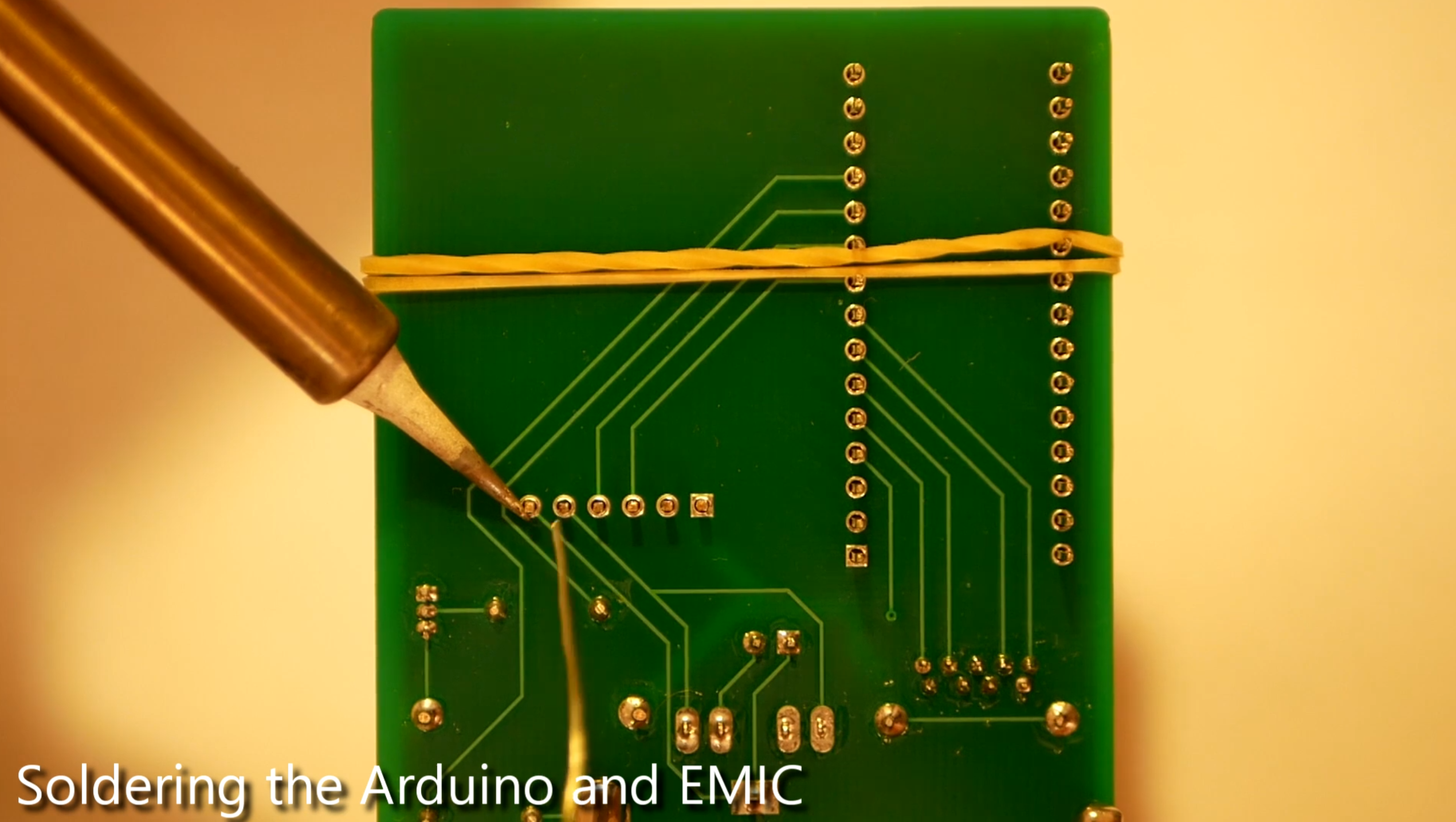
Discussions
Become a Hackaday.io Member
Create an account to leave a comment. Already have an account? Log In.
Wow, well put together! I'm going to coach some kids into finding people to build this for, and building it.
Are you sure? yes | no