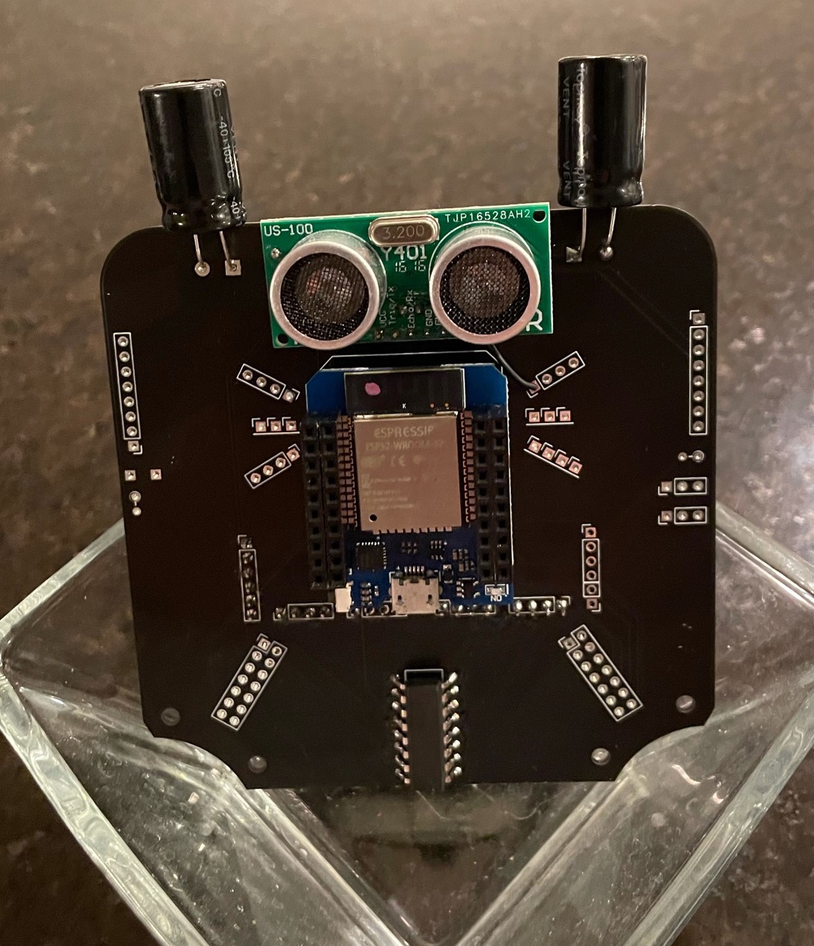
I got the boards back from JLCPCB in 8 days! They are about a $1 each plus the shipping so they ended up at $2.25 each for 20 of them. My brainboard is strategically sized within the 10cm x 10cm JCBPCB regular board size.
The whiskers are breakouts of the unused ESP32 pins. The soul patch is the HC74 analog multiplexer. The control pins are the fed from the PCA9685 PWM board. This allows the 2 I2C pins to control this analog mux as well. So I only need 3 pins to read all my analog sensor inputs in the legs and control the 12 control inputs on the motor drivers.
I stacked it with a socket and headers coming out of the ESP. I should be able to use most ESP8266 shields. I am starting with a 1.4 inch TFT screen. I intend to display the sensor outputs so I can understand how the angle sensors are working on each joint.
If you look carefully at the top right of the ESP, you can see my first bodge wire. I had planned on using the less expensive HC-SR04 and so I ran the 5V to it. However, since I do not have a level shifter between it and the ESP, I may fry it with the 5V communication. I changed to the 3V Y401 but my power pin had to run to the 3V whisker rail.
Tonight I am going to try to get to hello world on the TFT screen.
 shane.snipe
Discussions
Become a Hackaday.io Member
Create an account to leave a comment. Already have an account? Log In.