 shane.snipe
Well, yesterday was a combination of audible groans with a triumphant upswing toward the end of the day. My wife actually asked me if I hurt myself when I found out I soldered the foot components on in a way that would only work if the foot was facing backwards.
Here is what went well:
The screen is working! I have a dream of moving limb to a position, noting the sensor value and then moving it to the next. With enough granularity, I am hoping I can just ask the robot to go to these sensor positions and I will have a walking gait without the hard work of inverse kinematics.
Additionally I was able to connect to the PCA9685 board over I2C. It is outputting the appropriate driver signals to the leg flex.
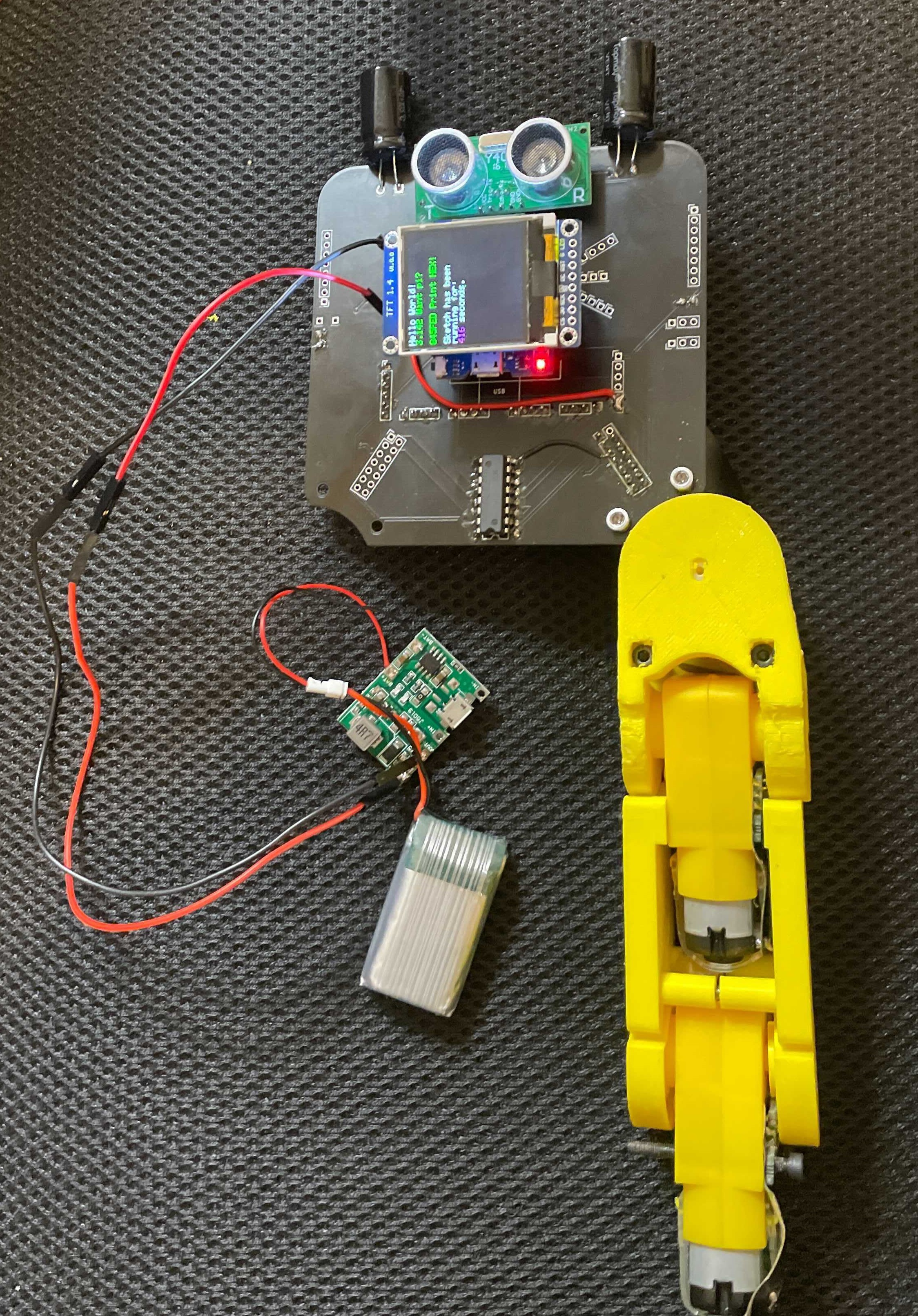
What worked after some bodge wires:
5V power to the device from a battery/step up regulator. The regulator will not go lower than 5.47V which is within the allowable voltage range for the ESP32 but I would prefer it to be 5V. I could put a diode in line which would drop it to 5V and eliminate the back voltage from the USB power during programming. However, to get the voltage working, I struggled and added wires. The 5V net is connected on the bare board but not on the one that was soldered. The 5V coming from the right leg and power pin of the ESP were not connected to the other 5V net even though I made a 5V power plane. I am considering just running discrete 5V traces on the next build and have a ground plane front and back.
Also the ground on the leg was floating. Looking back at Kicad, I saw an unconnected rats nest air wire. I had looked at the DRC errors but did not check the unconnected tab. There were grounds nearby so the bodge wire fixed that one and now I was getting nice signals down my leg.
What still does not work:
Although there were the correct signals gone to the the flex and presumable to my motor drivers, I did not get much more than some random twitching of the motors. For a while I got a consistent movement in one direction from one of the joints. I synchronized a LED pulse to coincide with the pulses from the PCA9685 board but most of the motor direction changes did not result in movement. This could be caused by broken flex connections, stick joints or general power issues. I probably should diagnose it before re-spinning the board.
I am also wondering if I can get enough power out of the 5V step up regulator. I would like to get the one from a power bank with a fixed 5V output.
Where trouble was expected but not found.
We had a lot of concerns about the 5V voltage from the battery and the one from the USB not playing well. So far, nothing was obviously wrong (read no magic smoke escaped) when both powers were connected at the same time. I was able to program while still running from the battery. In addition, I was able have the screen run all night long on a battery and it still was working in the morning. That almost sounds to good to be true. Maybe the display program turned off the wireless on the ESP to save the power but I was shocked to see it still running this morning. ( Might have had something do with a short night. I woke up at 4:30 with the PCB redesign punch list going through my head.)
What to do today:
1) Read sensors! Now that I can command the PCA9685 at will I can send the signals to the analog Demux chip and presumably put sensor reading up on the screen. In order to do that, I need to figure out how to display a variable on the screen and combine the I2C PCA9685 program with the display program. Hopefully they play nice together.
2) Re-spin board.
3) Make the daughter board with just he PCA9685, the demux and the flex connectors.
What is left untested.
1) I2S microphone. - This looks to complicated to get tested before my board spin. I will leave it and hope for the best.
2) MPU6050 Gyro - I have used this on every project I have done for years. It should be workable.
Board items to address:
1) Move PCA9685 board up to avoid the interference with the leg connectors and potentially the motor.
2) Narrow the pins on the Demux. Previously chose too wide a package and had to splay the pins to get it to work.
3) Use 2 ground planes and route discrete 5V power traces.
4) Take a hard look at 5V and 3V. Anything running on 5V needs a level shifter to avoid frying the ESP with the communication signals. The two components that need to be 5V are the ultrasonic transducer and the DF Player. Move the Gyro to 3V.
5) Implement said level shifter, potentially in the top right corner behind the ultrasonic sensor.
6) Put in some through holes to allow the daughter board to be connected with some long standoffs.
7) Add a 5V line to the board to board connector.
Flex items to address.
1) Motor terminals need to be through hole. To keep the adhesive, may 2 non plated through holes with a pad next to them.
2) Redo the charger an switch connections on the bottom of the flex. Find a new charge pump that is 5V and position the switch appropriately with wider spaced pins. Target no wires.
3) Move the through holes on the hip connection so the pads line up.
4) Consider reinforcing radii with unconnected copper planes. Seeing tearing.
Discussions
Become a Hackaday.io Member
Create an account to leave a comment. Already have an account? Log In.