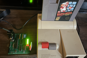
I will need two microcontroller GPIO pins from the PIC16F18446 for the latch and the clock signals to the controllers and a single return wire from each controller to the PIC16F18446 for the data; making 4 pins for the NES side of this interface.
I'm thinking that the PIC16F18446 will take care of continuously capturing the controllers state regardless of what spam 1 is doing.
I also need a way to select which of the two controllers should have it's value presented to the databus and there many ways that a port select could be implemented.
Also, if I want in future to connect Super NES controllers rather than NES then the serial stream is 16 bits long and so I'd need a way to select which byte of serial port I want presented to the data bus.
I could employ an 2 CPU control lines to select the controller to read, and 2 more lines if I used SNES rather than NES, but control lines are a preciuous commodity.
An alterntive is to first write to the interface selecting which value to present on a subsequent read. I would need a control line for the write, a control line for the read and the data written selects which device will be read. So only two control lines needed but the tradeoff is using two cock cycles instead.
In theory this two clock cycle approach would permit reading up to 256 distinct 8 but devices.
Exploring this approach further and considering how one would allow writing to many devices then an approach would be to use three control wires. One wire to write a device select byte, one wire to read the selected device, a final wire to select reading from the selected device. The device select register can be thought of as an extension to the regular set of control lines.
This extensible approach might be beneficial as I also want to add a random number source, and a pair of settable countdown timers as both are needed for CHIP-8, and probably a basic audio output device. All these addiitonal functions can be crammed into the PIC16F18446 I hope.
Pin count:
- 1 PIC16F18446 output pin for the NES clock signal
- 1 PIC16F18446 output pin for the NES latch signal
- 2 PIC16F18446 input pins for the NES data signals, one for each controller.
- 1 PIC16F18446 input pin for the device select write select
- 3 PIC16F18446 input pins for selecting which of 8 devices in the PIC16F18446 will be read or witten to.
- 1 PIC16F18446 input pin for the port read select
- 1 PIC16F18446 input pin for the port write select
- 8 PIC16F18446 output pins for the 8 bit bus connectionThat' a total of 18 GPI pins needed.
The PIC16F18446 provides 18 GPIO pins so that's right on the mark.
The devices would be:
- NES controller 1 (optional SNES controller 1 low byte) - readonly
- NES controller 2 (optional SNES controller 2 low byte) - readonly
- (optional SNES controller 1 high byte) - readonly
- (optional SNES controller 2 high byte) - readonly
- Countdown timer 1 - 60 Hz countdown - read/write
- Audio countdown timer 2 - 60 Hz countdown - read/wrire - beep is played while non-zero
- Random number generator - readonly
- (optional beep select - select the kind of sound the device will emit when the Audio countdown timer is > 0) - write only
Because the random number generator is readonly and the beep select is write only then these could share the same address.
It hasn't escaped my atttention that this device selection and read/write lines is somethink like I2C or SPI. Maybe I need to concentrate on adding one of those?
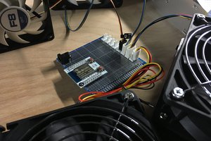
I've also considered using a 65C22 instead which would add to the nostalgia factor. but these seem quite expensive and the PIC's are really cheap and I have already got a few PIC16F18446 from my 7 Segment Module project (https://hackaday.io/project/178227-7-segment-hex-module-using-pic16f18446). The 65C22 would provide a load of timer stuff and also provide two bidirectoinal 8...
Read more » John Lonergan

 Dave
Dave
 Zachary Murtishi
 Albert Gonzalez
 EtchedPixels
Hi John, This is elaine from PCBWay. Thx for bringing us this thorough tutorial about your project. You just got a cloud of fans here. If you have any projects on the go which require PCBs , 3d Printing stuff, our pleasure to sponsor them for your project use. There might be a great start for us to build some partnership as well. Any interests, kindly contact: elaine@pcbway.com