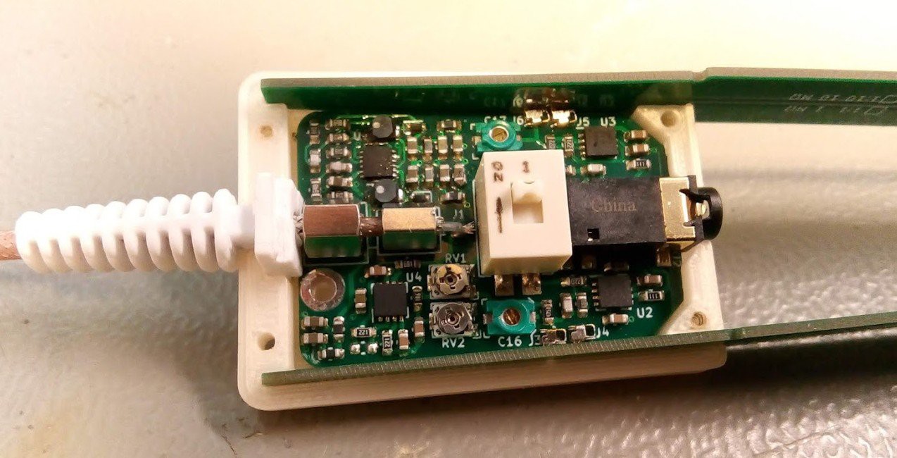
The second revision prototype switched to OPA659 for larger bandwidth. The tweezer tips are now attached using small spring contacts. The tip PCBs have a taper shape that will lock in place when pushed against the enclosure.

This version also added a gain switch to select between 2x and 20x amplification. The 2x output stage gain is always included because it extends the common mode voltage range of the input, while the input stage can have either 1x or 10x gain.
The initial plan was to use a 3.5 mm jack with shielded cable for the probe accessories. The input impedance is 500 kohm, so matching it with a coaxial cable is not possible - and the cables can be kept short enough to not need matching anyway. The common audio cables seemed a reasonable low-cost option, but it turns out PVC insulation in them has a huge variance in capacitance. It varies both by frequency and by temperature, making it impossible to properly compensate the inputs. Real coax connectors will be needed.
Otherwise the second prototype works well and has a bandwidth of over 100 MHz. There is a bit of noise issues, and some thermal drift on startup. These can probably be improved by adjusting the PCB layout.
 Petteri Aimonen
Discussions
Become a Hackaday.io Member
Create an account to leave a comment. Already have an account? Log In.