Main design considerations
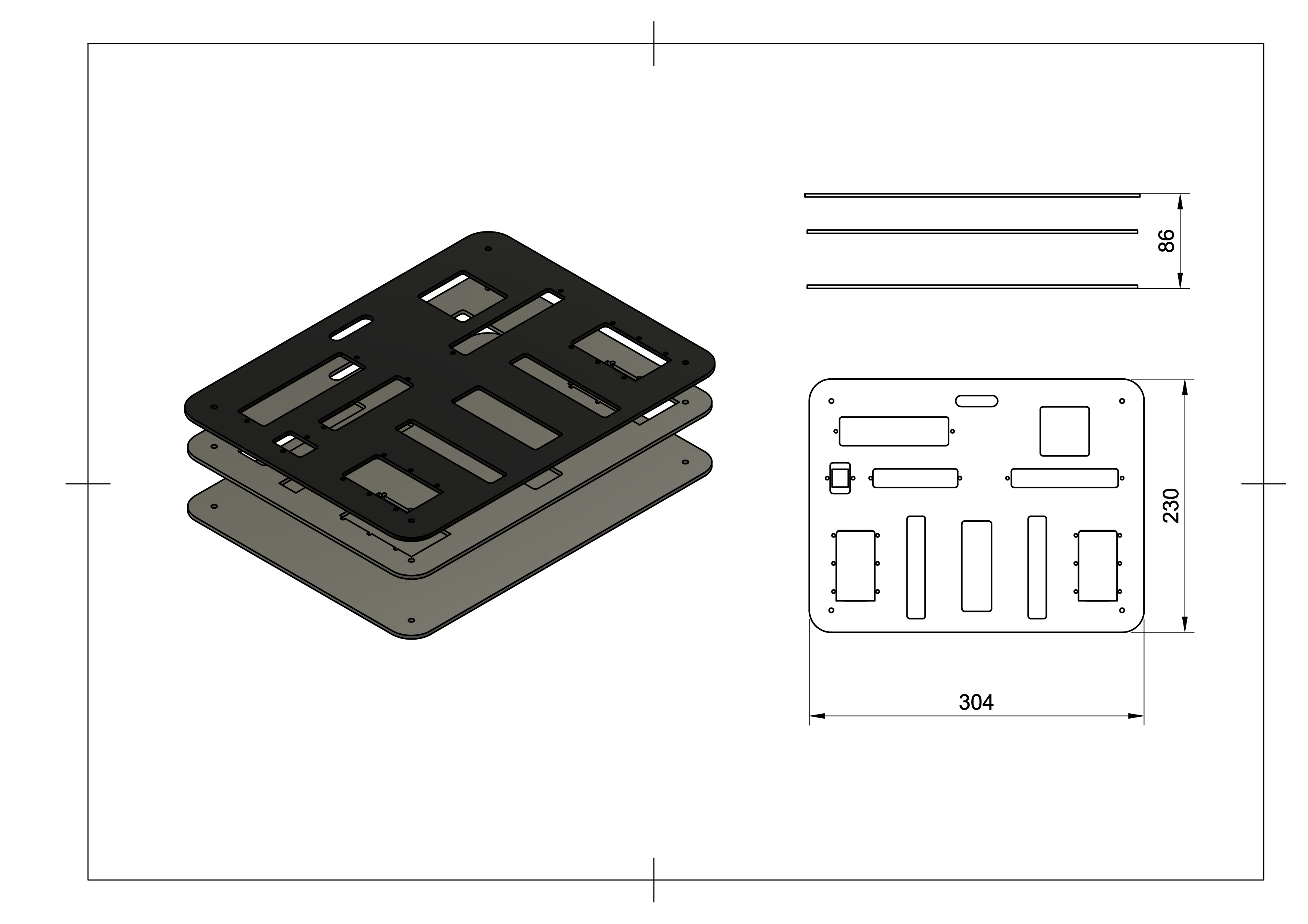
As the name of this log suggests, the design of the bottom section of the case was done in a stack configuration. I previously mentioned that I would avoid modifying the case so that it retains its weatherproof capabilities. The bottom half of it doesn't have anchoring points where the stack can be fixed. As it will have a considerable weight and won't be subject to any weird forces, I opted to leave the stack free. Don't panic. It fits quite snuggly and shouldn't come out unless the case is open and it suffers from a hard fall. While the case is closed, the idea is to make the height just big enough so that the top panel makes contact with the stack and it doesn't move while transporting it.
The stack consists of 3 layers held together by 4 threaded screws. The panel on the top holds the visible components, namely the joysticks, ports, fan, and any I/O. It also has a cutout matching the one on the top panel (lid), for cable routing. The bottom layer hold the Nvidia Jetson Nano, the Arduino Mega2560, power regulating circuits and (as a future upgrade) batteries. The second/middle layer is more of a separating layer that prevents any possible contact between the I/O and components mounted on the bottom layer.
Attention to detail is one of the aspects that characterizes this project. Yes there are quite some aesthetic fails but during the design phase I kept thinking about how everything would be fabricated, and always considering the best way to achieve something neat. The panels were cut using a flimsy CNC laser engraver I built a while back to experiment with brushless motors in CNC projects. Knowing its limitations, I preferred to cut the holes in the panels and cover the cut edges with more precise and clean 3d printed parts. As an example, the vents on the top lid panel could have been made cutting directly the panels, but preferred to cut the holes and 3d print the vents.

As far as airflow goes, the fit allows for air to go in through the edges of the stack and is sucked up by the fan placed on the panel.
The joysticks
As simple as this might seem for some, I believe these components deserve their own section. Deciding what to do with the protruding joysticks required a couple of iterations. Let me start off by mentioning that I didn't want to use the so known (Playstation like) half-ball-shaped joysticks. These take the most importance out of every control and need to be comfortable and allow fine control of the robots.
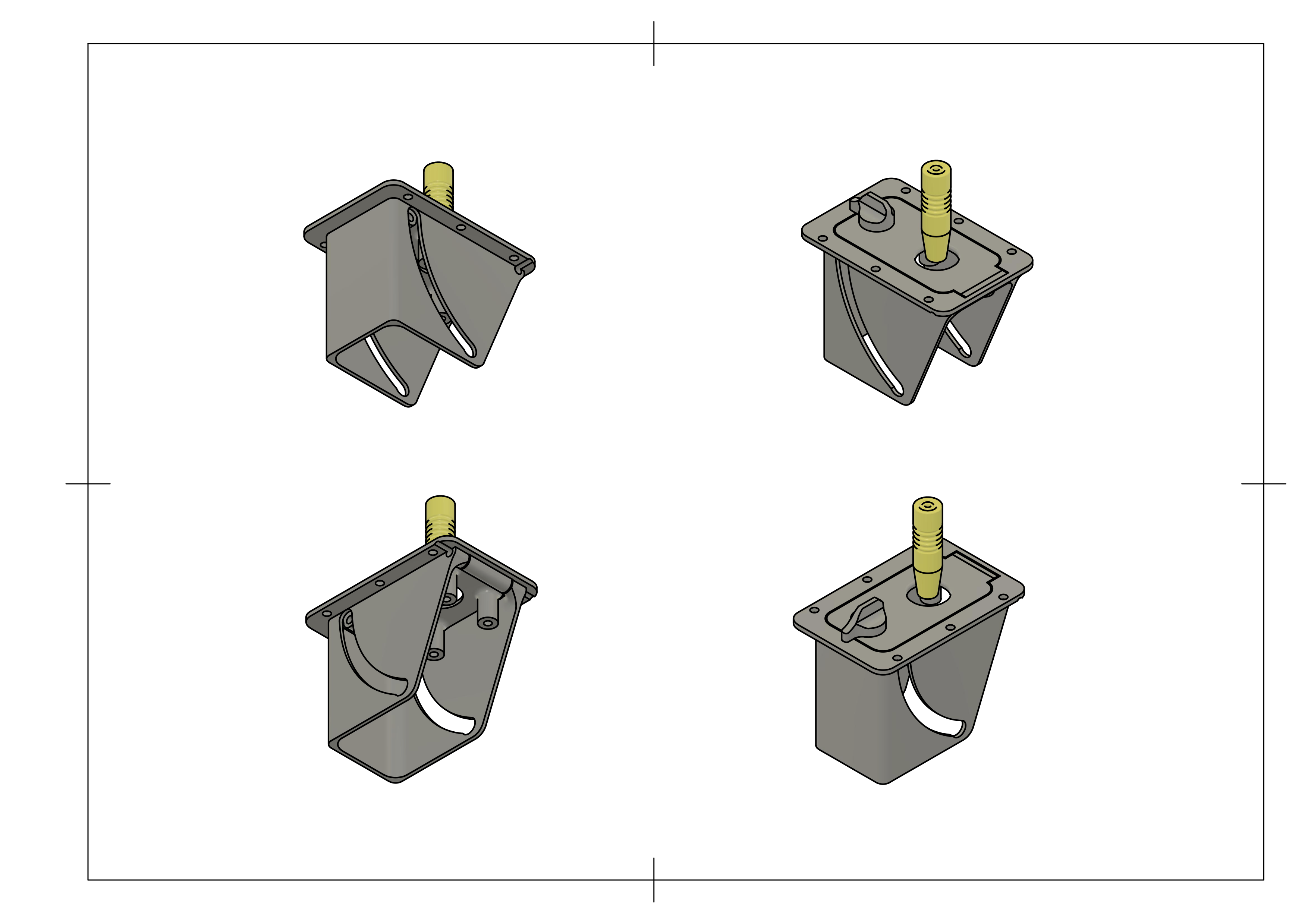
The sticks could have been made removable, but I preferred to make them foldable with a lock mechanism. The whole base pivots on an axle, and a knob let's the be locked in place for when in use. A spring loaded mechanism could have been nice so that when these aren't locked, they stay retracted. As of today, this isn't the case and when the lock isn't on, they can pivot [quite] freely. The lock prevents them from folding when in use, and screws prevent them from exceeding their upright position.

The turning lock is held in place by a screw which is fixed to the knob and spins (with a bit of resistance) through the folding tab. The casing is made to [1] prevent anything from getting in the way of the folding mechanism and [2]limit the range of motion of the pivoting tab. Two screws slide though the channel and make contact with the casing on the limits of the displacement range. The yellow stick is actually held in place by the joystick pcb which is not modeled.
 Maximiliano Palay
Discussions
Become a Hackaday.io Member
Create an account to leave a comment. Already have an account? Log In.