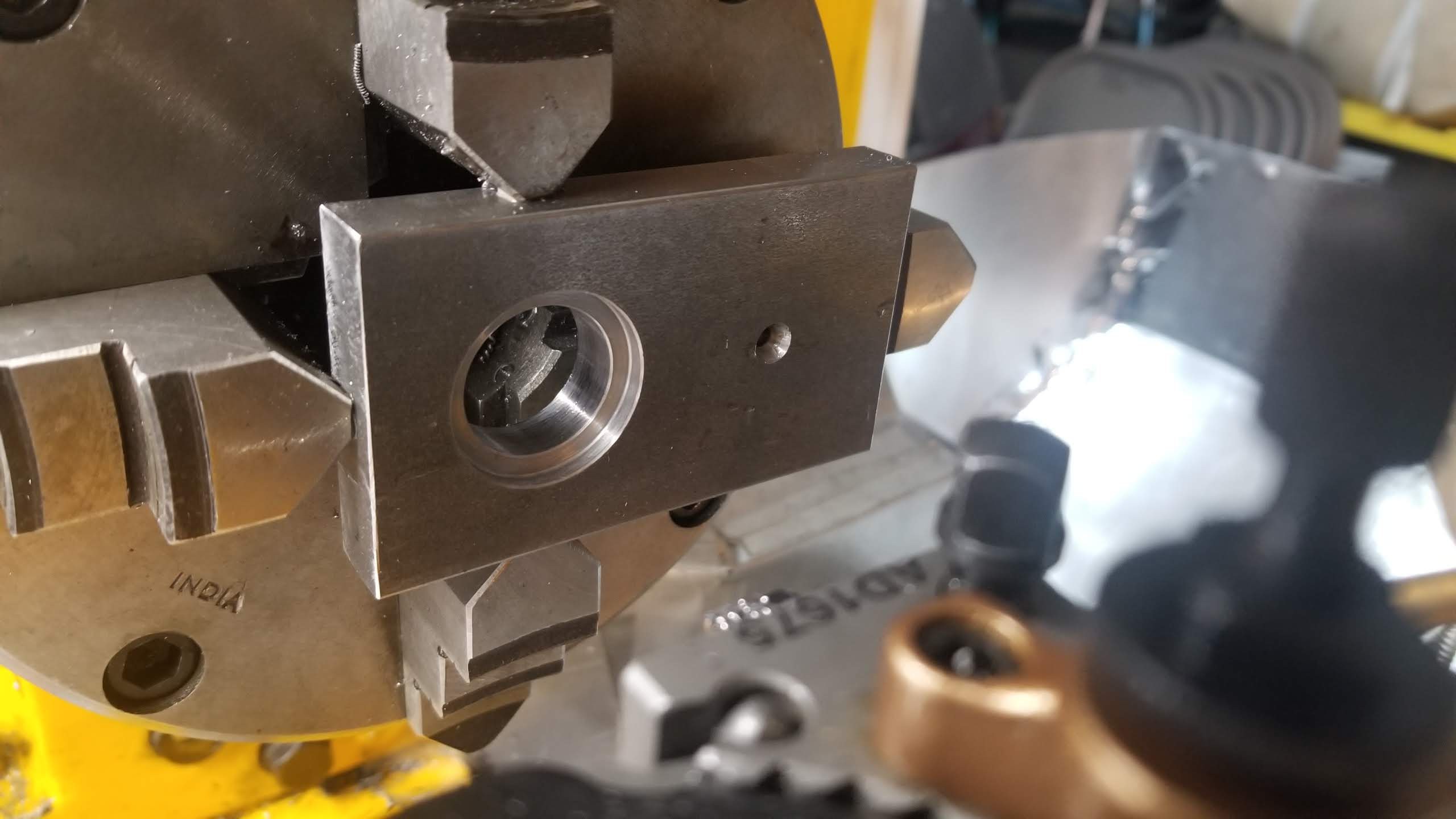
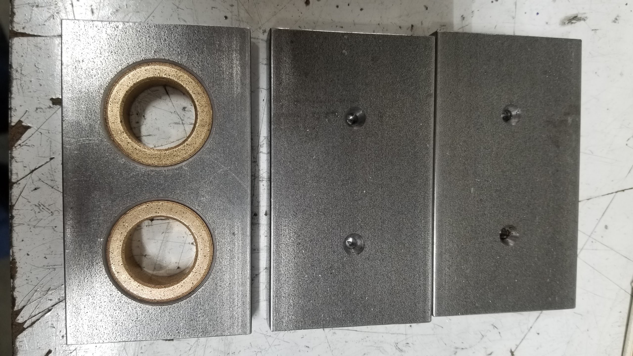
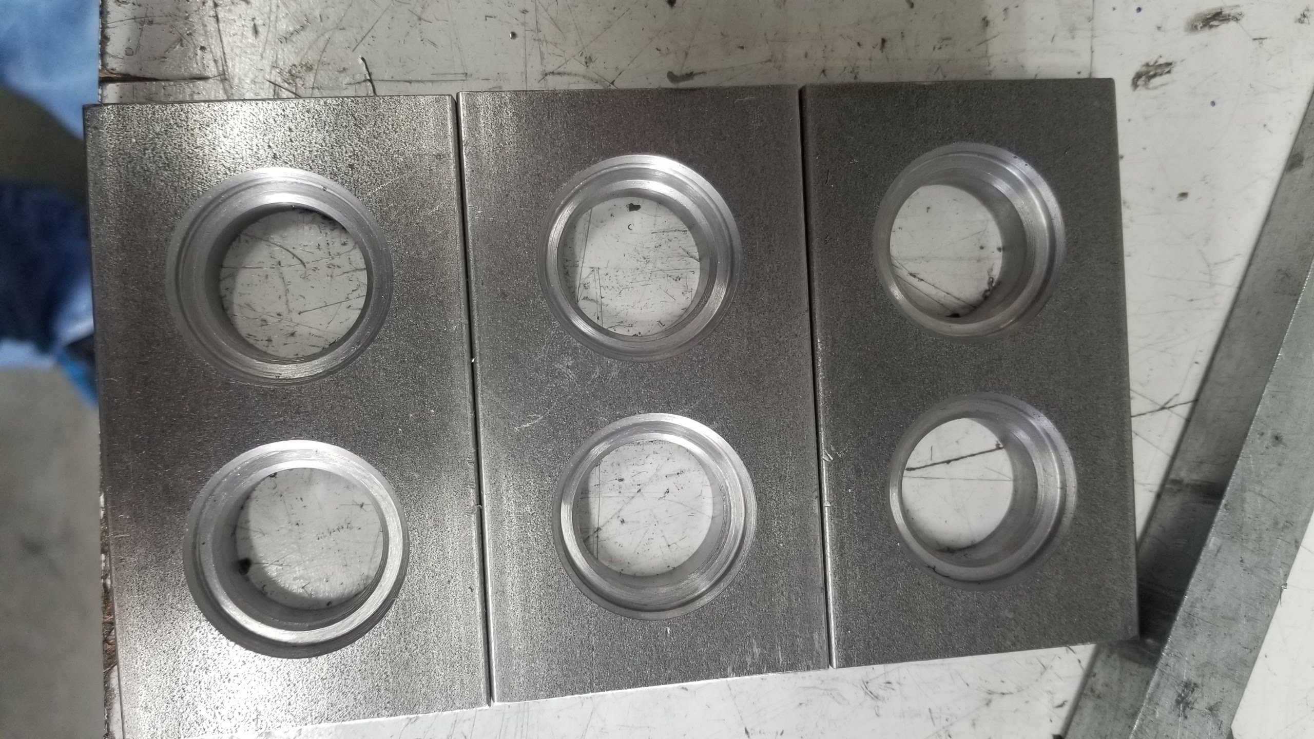
This is my first real use of the CNC to make something. This is a project I am doing to make a penny squashing machine. Because the forces involved are huge, the frames are in 1/2" 1018. The plates were all squared identical on the mill and the center drills for the holes also marked out on the mill. I used these to indicate in the part in the 4 jaw chuck using a 2MT dead center on 3MT-2MT extension in the 3MT-3MT extension mounted in the tail stock. Parallels behind the part to make it flat, removed after indicating. The dial indicator resting on the extension at the nearest ground location.
Then I drilled out most of the material for the bearing holes. I bored it bit by bit the first time and hand crafted the g-code as I went, wrapping the already-run code in
O100 WHILE [0]
O100 ENDWHILE
until I got the feeds and speeds and chamfers right.
Then it was pretty quick to iterate through the other five, though I always stopped to check the bore diameter before running the final pass.
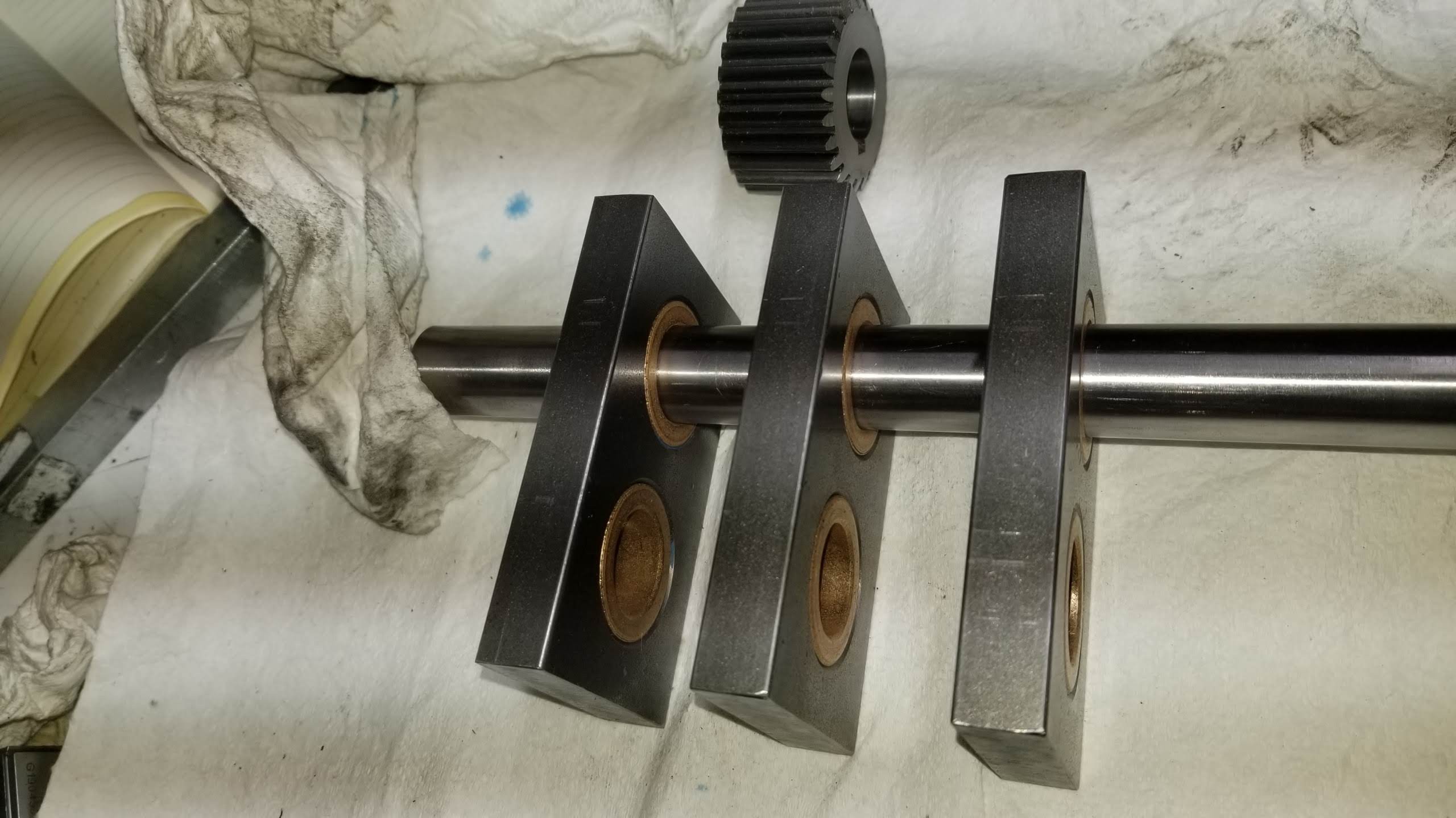
The bearing bores are for 3/4" drill rod.
Things learned:
- Side milling the ends of the plates with the 3/4" 4 flute mill came out very un-square across the thickness. Tramming? Flex? I was able to end mill them square and there is enough clearance at the ends that having them a bit shorter (but all the same) is ok.
- The 6" 4-jaw is a little too big and the 8" faceplate it is mounted to is much too big.
- I really want to see if I can move the table linear scale to the other side - away from the chuck. I think it make be possible by rotating the the thing it spins on. I can't just bolt it on the other side as the gib is there.
- The table had gotten out of square, so I should re-check it every time I square the vise.
- More splash control/chip guards still needed. And a holey rubber mat. I'm getting yelled at for tracking chips into the house.


The gear in the picture is cut from McMaster gear stock.
 Alastair Young
Discussions
Become a Hackaday.io Member
Create an account to leave a comment. Already have an account? Log In.