 Paul McClay
tl;dr: Minimal appears able to produce finer PCB features than common low-end generics.
To what existing baseline can we compare Minamil's PCB milling capability?
The "cheapest" CNC
As of August 2021, it looks like the dominant “cheapest” CNC machines for PCB routing[note 1] and other (very) light hobby use are variations of “3018” - a generic design with 30cm x 18cm work area, and typically 4-5cm Z travel. Other “xxyy” designations indicate similar machines with larger or smaller work area. Various sellers offer machines of very similar design built to various levels of cost & robustness. Current examples listed by Amazon include: basic <$150, “pro” ~$200, and “max” ~$300.

Smaller machines of similar kind include essentially all the same parts and do not cost very much less. Construction from shorter lengths of similar linear rods & extrusions may give smaller units greater stiffness.
I have not yet found where this design comes from, or when. My current best guess is that “CNC 3018” was already generic before English speakers wrote much about them on Teh Internetz. Please comment if you know.
Not having one myself, I don’t really know what they can do. After a bit of searching I’ve found several mentions of milling/routing PCBs on these machines, but little indication of use for very fine pitch components or high density of small features.
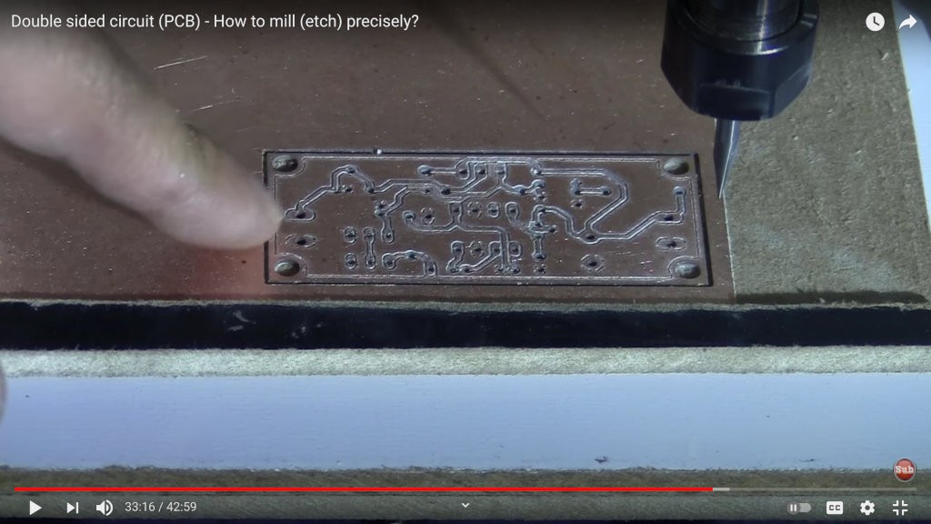
- At the beginning of this year, Electronics Weekly blogger Steve Bush wrote one of the better overviews of this category that I’ve found so far. That post was the second of a two-part series. In the first part he wrote “However, like so many people before, I am tempted to have a go at modify[ing] the little cnc to [...] have, maybe, 0.2mm accuracy with softer stuff [than aluminum]”. He recommends a youtuber’s videos, one of which details how to mill a PCB “preceisely” on a 3018. That video, from Sep. 2019, shows fairly coarse through-hole features:
![]()
That gives data points at "0.2mm accuracy" and coarse through-hole (0.1") scale PCB features.
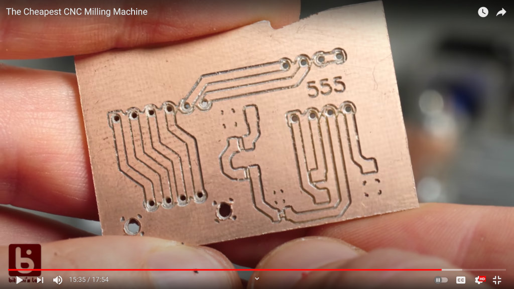
- YouTuber bitluni’s video “The Cheapest CNC Milling Machine” from April 2020 shows a failed attempt to cut SO (0.05”) pitch features, and then a usable result with 0.1" through-hole and sparsely placed 0603 discrete surface-mount parts:
- YouTuber HomoFaciens, specialist in building high function from extremely low tech/cost inputs, posted a video “Isolation milling a PCB with the CNC 3018Pro from Mostics” in Feb. 2021. It shows his spindle running with obvious significant runout and he produces a board with coarse through-hole features:
- Teaching Tech’s Oct. 2020 video “Homemade custom PCB guide using free KiCAD software” discusses design compensation for wide milling tracks and shows a board with coarse through-hole features and thinned tracks:
- For a non-graphical example, guidance at Hackerspace Nijmegen (currently displaced due to COVID-19) advises minimum 0.5mm separation with between traces: "Milling PCB's with 3018 Chinese Desktop CNC"
- DIY TECH BROS on YouTube have the cleanest example that I've found so far. Their “CNC PCB - high quality with the budget 3018 CNC” shows, with dramatic flair (a la WEGSTR CNC?), a clean SO-pitch breakout board. From the photo, I think it looks like their isolation path width is about 0.2-0.22ish mm.
In a very extensive tutorial series + discussion "Milling PCBs with cheap Chinese "desktop" CNC-router" spanning Aug 2018 to Sep 2020, author esaj reports "I've made boards with 0.3-0.4mm traces". Although he doesn't focus on fine-pitch parts, his sample photos show some very finely cut traces. If I've figured right, this photo crop below shows isolation grooves cut as small as ~0.18mm:

source He reports generally configuring 0.15mm as a tool diameter for isolation path generation when cutting with 0.1mm 30° V-bits, and discusses tool & path parameters at some length.
He tried a high-rpm motor upgrade for a while but abandoned it. About speed and runout, he reports: "I usually run the spindle at full RPMs [...]. With the original 7k or 9k (I no longer remember which it was) RPM motor and ER-11 chuck, there's very little runout. With the 20k RPM motor I had in use for a while, the runout was often way too much for higher RPMs, so I couldn't run it really at full speed most of the time (although sometimes it just "worked" and I could get good cuts at 800mm/min)."
About depth of cut in FR4, he recommends very shallow cuts, even taking the shallow isolation cuts in two very shallow steps.
Nine months into that thread, he reports "Looks like I found the limit of the machine tolerances on the CNC" with 0.1mm traces on 0.5mm centers for an MSOP package:
![]()
source The next day esaj reported: "I ran another board today, with slightly different settings (slower cuts, first with 30-deg 0.1mm bit at 100mm/min, then again with 15-deg titanium 0.1mm bit to clean up). This time the traces are closer to 0.2mm." With isolation paths reduced from 0.4mm to 0.3mm.
![]()
source These two are the only examples of milling a 0.5mm pitch footprint on a 3018-type machine that I've found, neither case leaving the intended 0.3mm breadth of lands for the package. While I think the first image shown above from his tutorial shows sufficiently narrow ~0.2mm isolation paths, he apparently did not succeed in replicating that at will for this small footprint. In discussion he attributes that to "motor + bit vibration".
He did populate the board with 0.1mm traces, apparently successfully:
![]()
ibid.


So it looks like the baseline for PCB milling on "cheapest" desktop CNC machines is mainly around through-hole or 0.1" pitch density, with best case examples of clean SO/0.05" pitch or marginal 0.5mm pitch footprints.
"Minamil"
For the comparison, here is an image crop from a July log entry about milling an SSOP footprint:
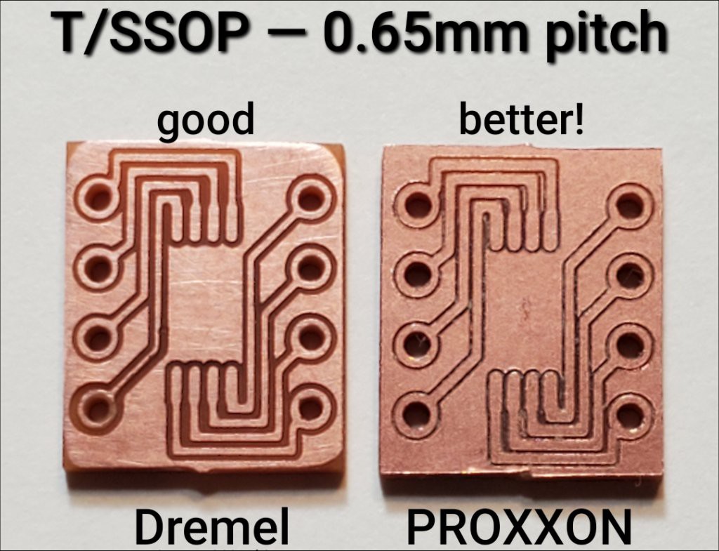
While the SSOP footprint has pads on 0.65mm centers instead of 0.5mm, the horizontal traces crossing each end of the DIP footprint lie on 0.5mm centers. Using a beater old Dremel for a spindle, Minamil[note 2] cut isolation paths slightly narrower than half of that interval, or <0.25mm wide, leaving traces at least wider than 0.25mm if not fully 0.3mm wide for nominal 0.5mm pitch footprint. Cutting the same part using a PROXXON IBS/E for a spindle left traces over 0.3mm wide on 0.5mm centers separated by isolation paths under 0.2mm wide. So far I haven't found an example of a "cheap" 3018-type CNC router matching that.
Advantage: Minamil. For less cash in a smaller footprint.
In the baseline case, it's pretty clear that the 775 motor spindles contribute to spreading out minimal isolation path width by runout and vibration. Also relatively low speed for standard motors -- 8k to 12krpm -- limits cutting edge speed for tiny tool diameters, and limits feed rate.
Minamil uses a general-purpose rotary tool, which will almost certainly spin up faster than the 8k-12k rpm range for typical "3018" spindles, and may achieve lower runout than most 775-derived spindles.
Because the vertical axis must necessarily have a counterbalance, Minamil can easily accommodate the greater mass of a general-purpose rotary tool.
A general-purpose rotary tool has a cost advantage in that it can earn its keep doing other stuff when not making PCBs.
Notes
- So is it "mill" or "router"?
I wrote a little about that earlier. I doubt there is a concrete specific answer. My over-simplified rubric goes like this:
- Router - Relatively compact/light Z axis moving laterally (say, X) on a gantry (that may also move in Y) around a relatively large work area. Typically broader than tall. Penalizes Z mass because axis & spindle accelerate and move in X or XY plane.
- Mill - Relatively massive fixed Z axis with spindle moving only in Z, maybe ponderously, while relatively small work area moves in XY underneath fixed Z. Typically taller than wide. Z axis and spindle may be much more massive & slow relative to XY table.
Always exceptions; if your gantry has an operator’s cab, please call it anything you want.
Also from the earlier log entry: “... And the pretentiousness of calling it a "mill" hides in plain sight the pretentiousness of calling a toy-scale device a tool at all. Kind of like an Easy-Bake® "oven".” But seeing that it works, I don't mind calling it a tool.
- "Minamil" essentially as published but with a modified Z axis that I haven't published yet. I think that won't make a huge difference.
Discussions
Become a Hackaday.io Member
Create an account to leave a comment. Already have an account? Log In.