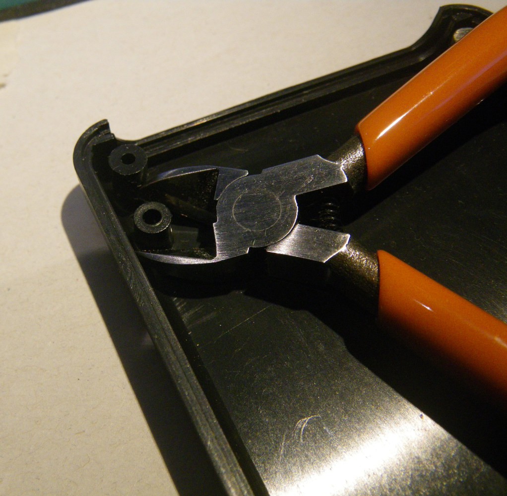
- Two unused mounting points in the "top" of the case need to be removed to provide clearance for the screen.
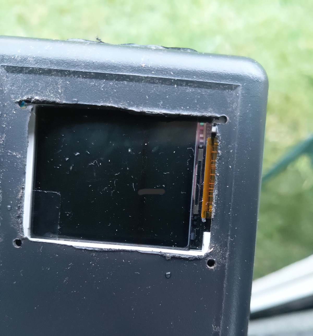
- The top of the case also needs holes for the switches, and a big rectangular cutout for the screen. Start with smaller holes than you think you need, then check for alignment. You can also use the PCB as a guide, or a copy of the PCB printed on paper. If you use a paper printout, you can drill right through it if necessary.
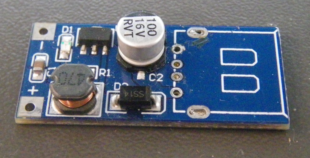
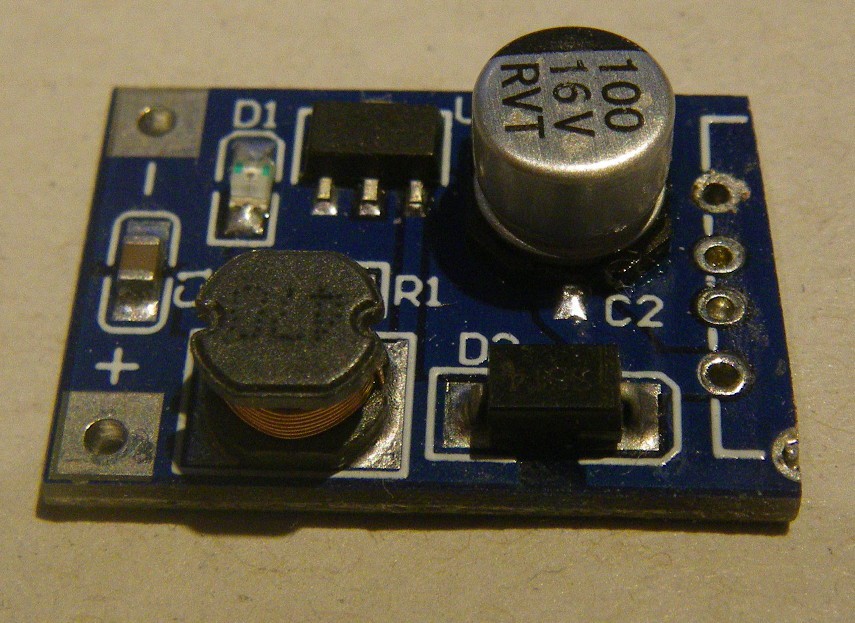
- Depending on the DC-DC module, you may need to modify it to fit. I had to remove the big USB socket and then cut down the module's PCB. A hacksaw with very fine teeth works, or you can deeply score the PCB with a knife and then bend it until it snaps along the cut.


Discussions
Become a Hackaday.io Member
Create an account to leave a comment. Already have an account? Log In.