 David H Haffner Sr
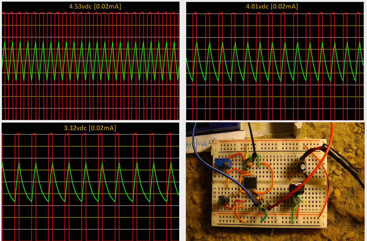
While I am waiting for some component parts to arrive this week, I modified my 555 timer pulse generator test circuit to be in sync with the TCD1304's Master clock sequence. I used an L7805CV 5vdc + voltage regulator and 2 well placed ceramic disk capacitors at pins 6 and 3, to smooth out any ringing and keep a lot of the noise down and got the pulses to be quite tame.
I am providing my schematic design and plots, along with the mathematical equations to solve for T1 and T2 timing sequences.
Timing is set at 10ms at a frequency of 470 Hz (due to L1 (470uf fixed induction coil at pin# 3)
The circuit can be further modified to be a mono stable circuit by untying pins 2 and 6, use pin 2 as the triggering incoming pulse and make reset and trigger input (pin# 4,) momentarily low to reset timing cycle, otherwise keep reset at vcc.
Below is the schematic for the circuit in the picture above:
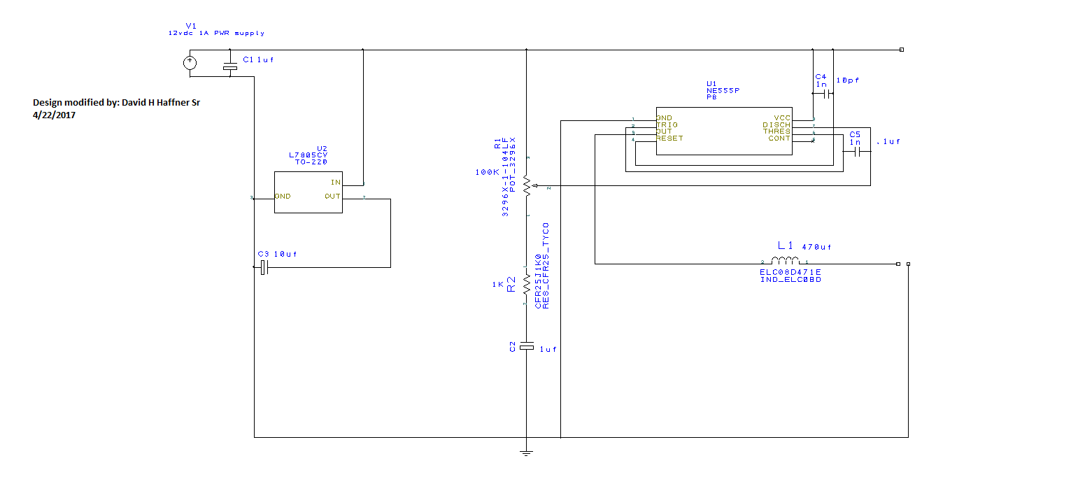
L7805CV voltage regulated Pulse Generator using a 555 Timer
12vdc supply voltage
L7805cv volage regulator
R1 = 100k (trim POT)
R2 = 1K
C1 = 1uf (electrolytic/35v)
C4 = 10pf
C5 = 0.1uf (ceramic/104m)
C2 = 1uf (electrolytic/35v)
C3 = 10uf (electrolytic/35v)
L1 Induction coil (470uf/7.09ohm @ pin# 3)
Solving for Timing sequence of T1 and T2:
T1 = .693(R1+R2)C1
T2 = .693(R2)C1
Frequency = 1.44/(R1+2R2)C1
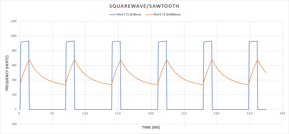
The plot above was done on processed using Excel
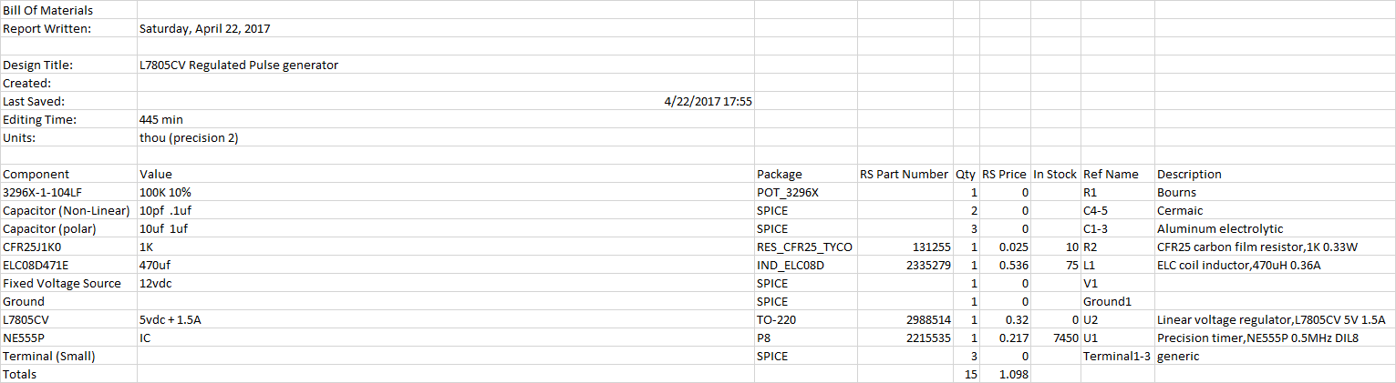
Bill of Materials (BOM)
Discussions
Become a Hackaday.io Member
Create an account to leave a comment. Already have an account? Log In.