 David H Haffner Sr
Well exactly 98 man hours later, (avg. 14hrs per day*7,) and These are the 2 primary modules and I included the CLI (communication link interface) I had to make this so I could connect the CCD module with the ADC module.
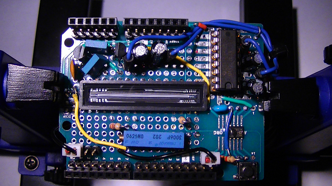
This is the CCD module (1)
This is the ADC, module (2) Top view
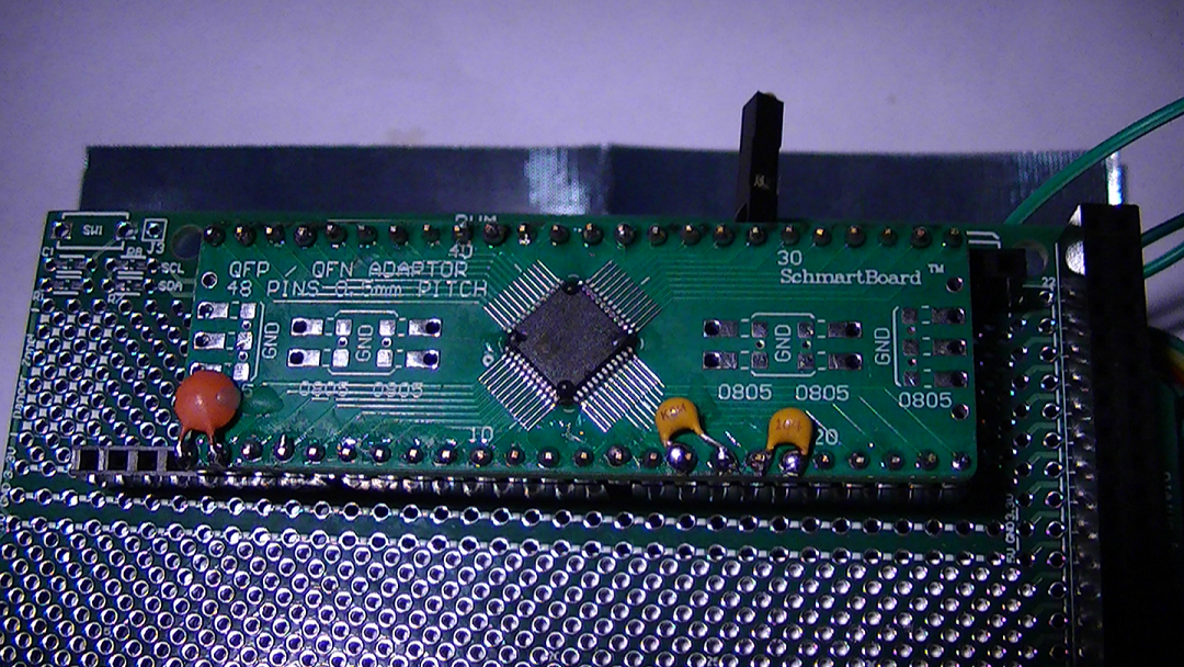
Below is the bottom view
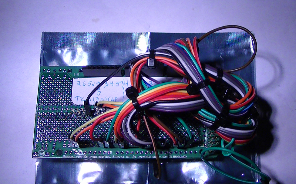
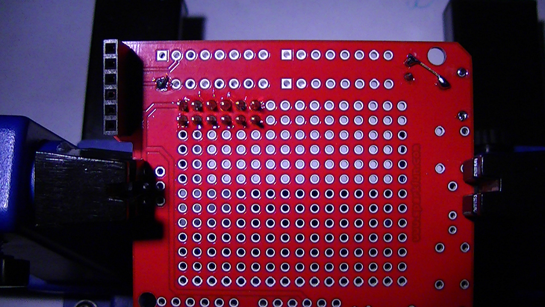
This is the CLI, Top view (which will be connected to the inside front face of spectrometer
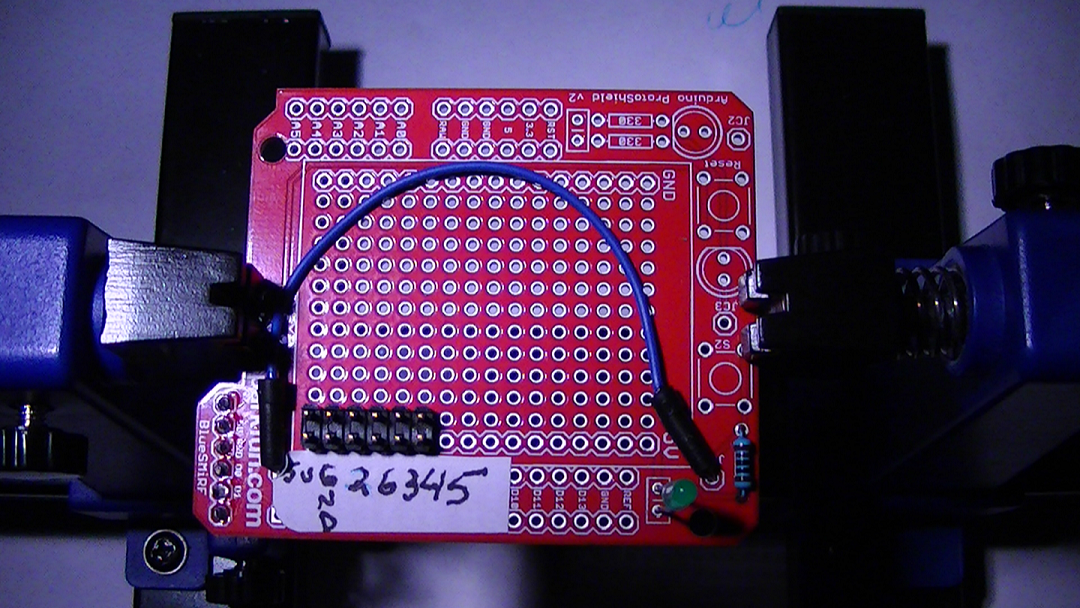
Below is the backside view of CLI, CCD module (1) connects to terminal on the left and above view, the 2 x 6 dual terminal with the power indicator LED, faces toward user for connection to MCU and ADC module.
This is the top cover of the MCU chassis, the trigger switch is already in place with the science frame indicator LED visable

Close up view of the trigger switch circuit
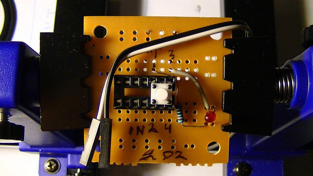
Below is the backside view of the switch already mounted in place

In case you were wondering why there is a 14 pin DIP socket securing the switch? Well, this is a little blast from my past, it was suppose to be a project for a function generator and evidently I never finished it, so I decided to put it to good use anyway :)
Discussions
Become a Hackaday.io Member
Create an account to leave a comment. Already have an account? Log In.