 David H Haffner Sr
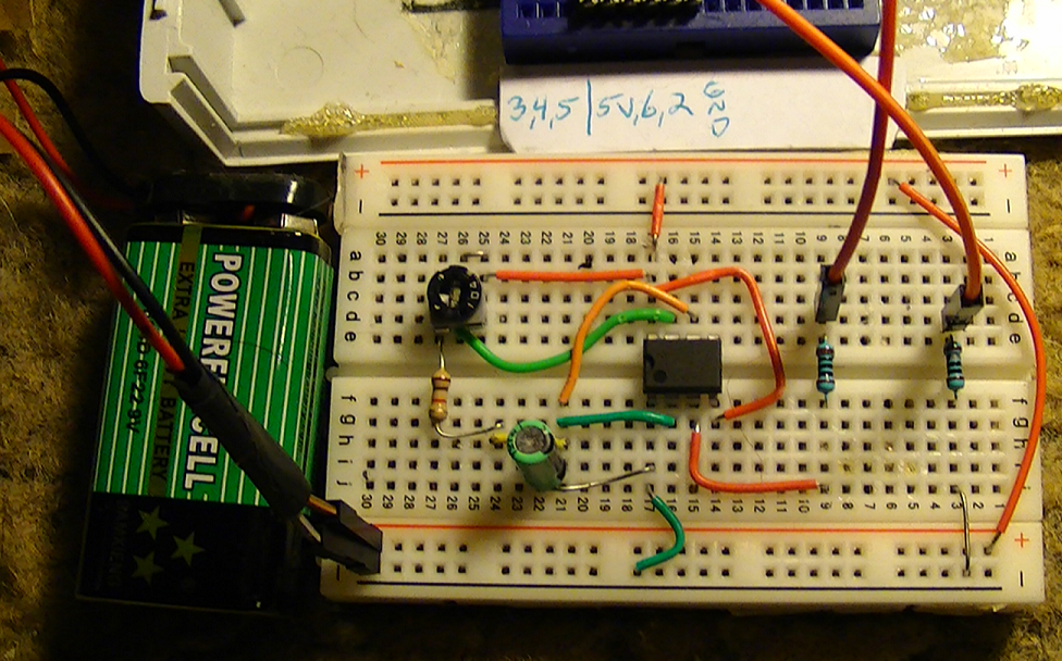
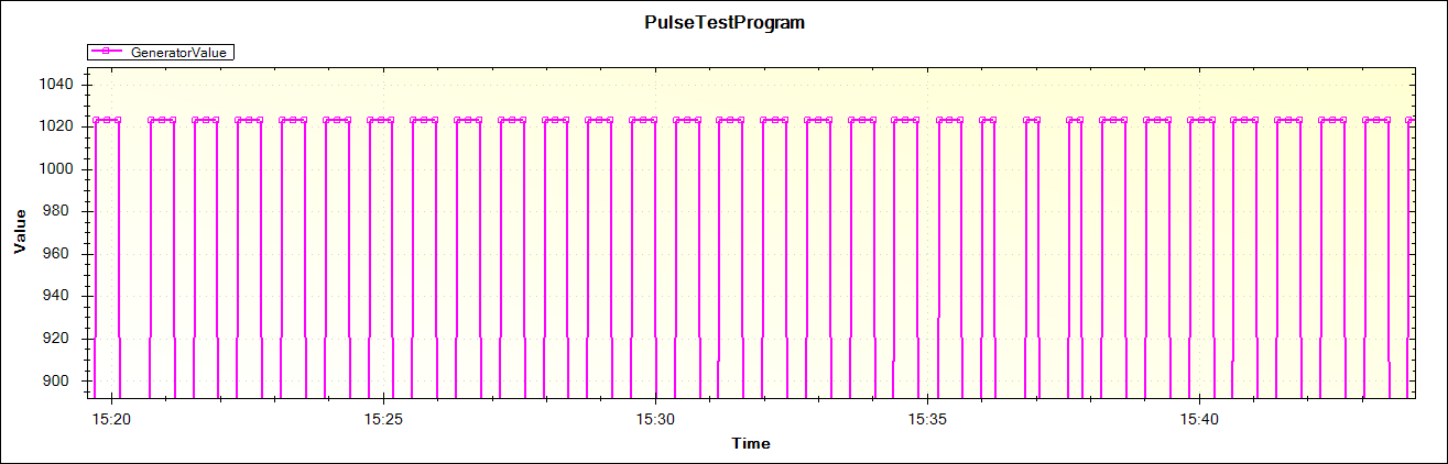
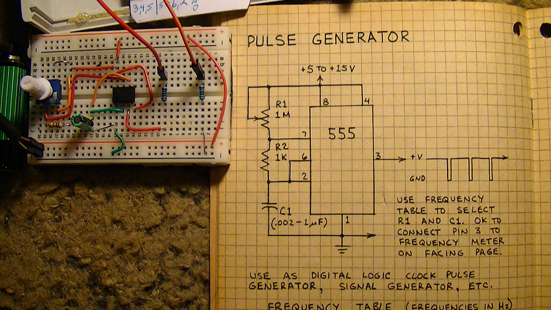
I put together a simple pulse generator, using a 555 timer chip from a schematic from an old Forest Mims notebook of mine, so I could calibrate the MCU and MegunoLink Pro to work together when I get ready to link the CCD to the ATmega1284.
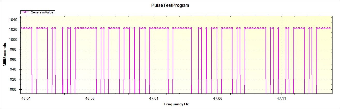
These are the results below and they are beautiful :)
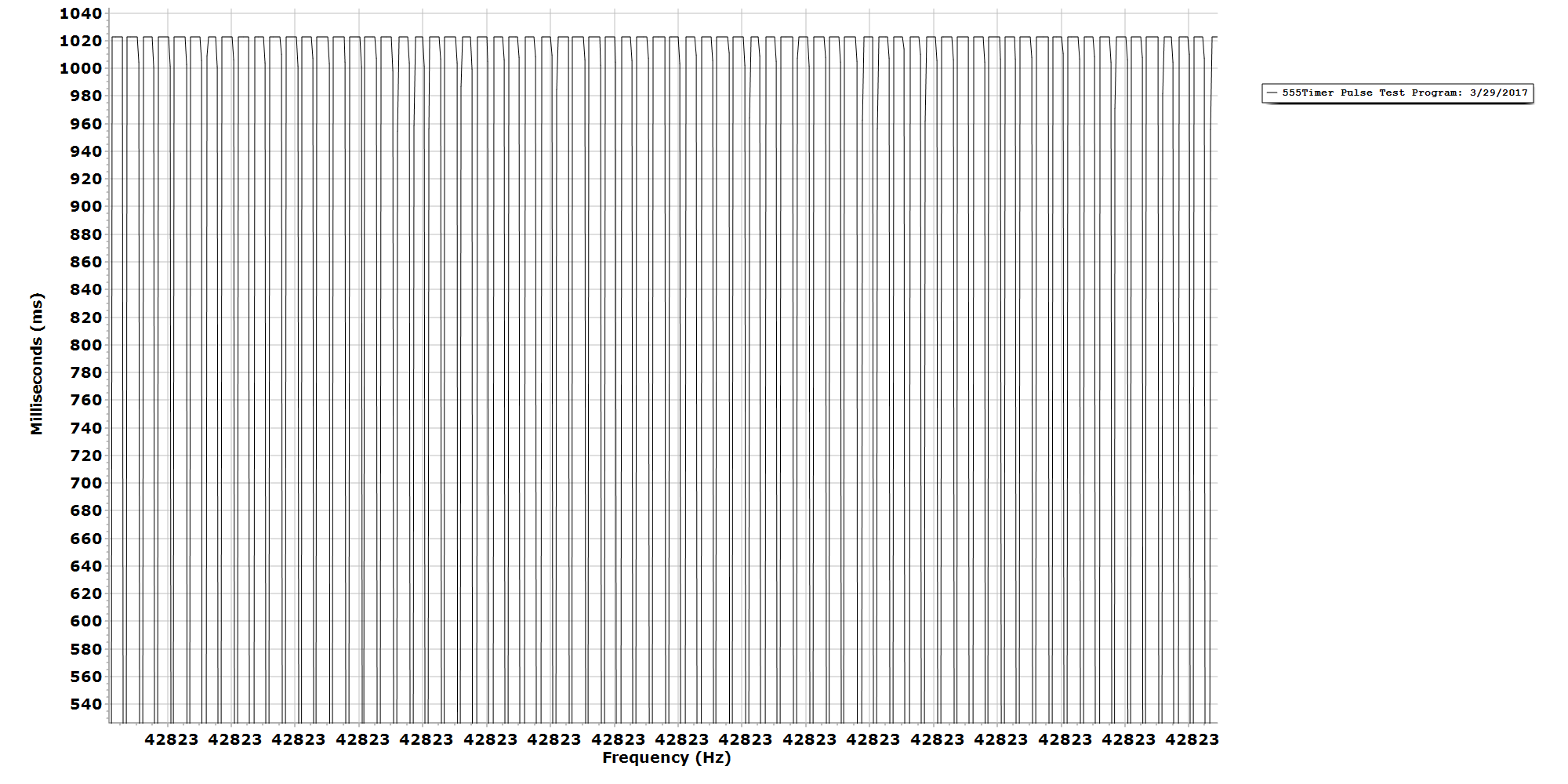
Final Plot, 4.47vdc @ 0.26mA
Code used for this test;
#include "MegunoLink.h" // Helpful functions for communicating with MegunoLink.
// Millis value when the data was last sent.
long LastSent;
// Interval (milliseconds) between sending analog data
const unsigned SendInterval = 200; // [ms]
// The plot we are sending data to.
TimePlot MyPlot;
void setup()
{
Serial.begin(115200);
LastSent = millis();
MyPlot.SetTitle("PulseTestProgram");
MyPlot.SetXlabel("Frequency Hz");
MyPlot.SetYlabel("MilliSeconds");
MyPlot.SetSeriesProperties("GeneratorValue", Plot::Magenta, Plot::Solid, 2, Plot::Square);
}
void loop()
{
if ((millis() - LastSent) > SendInterval)
{
LastSent = millis();
int DataValue = analogRead(PA0);
MyPlot.SendData("GeneratorValue", DataValue);
}
}
This plot is using a 10k Pot @ 4.53vdc
Pulse at 4.98vdc
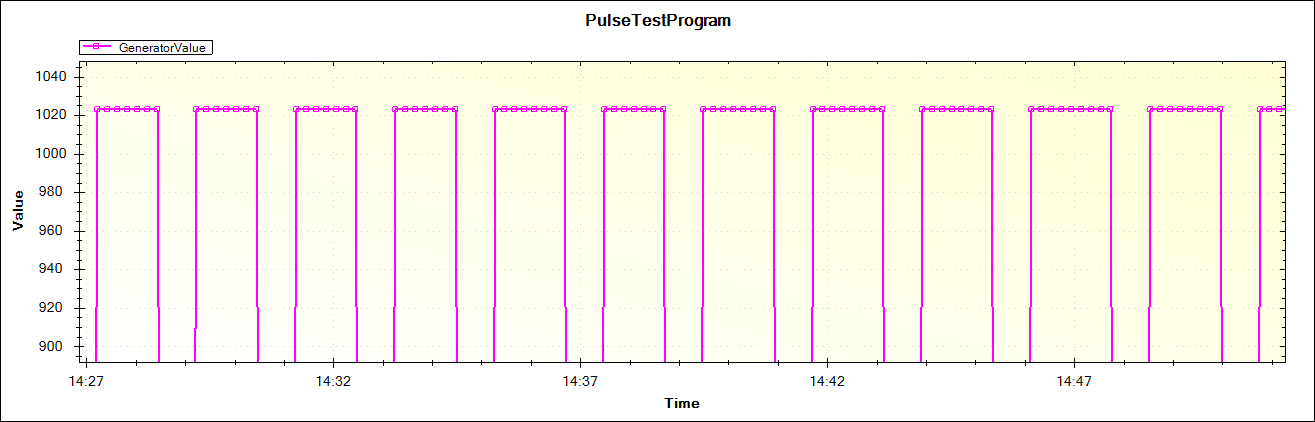
Pulse at 4.13vdc

Pulse at 4.27vdc

Discussions
Become a Hackaday.io Member
Create an account to leave a comment. Already have an account? Log In.