 David H Haffner Sr
This is REV B of my Mega 2560 stepper Motor control circuit driver control board, I had to fix the switches as they were not working properly, now they do since I debounced them, I am posting a YouTube video showing it's operation
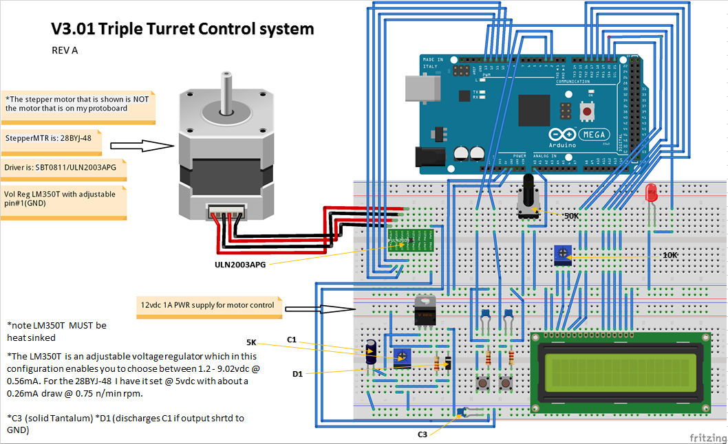
Below is the Arduino breadboard schematic showing the entire layout;
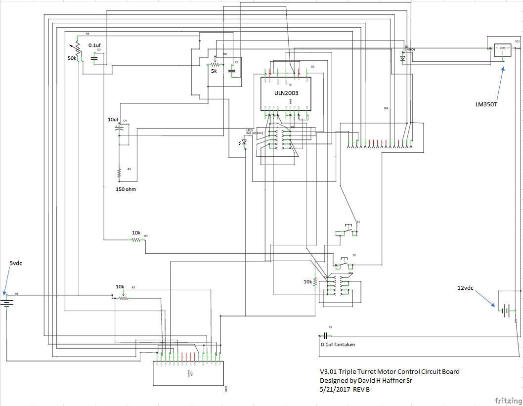
Next is the Fritzing schematic;
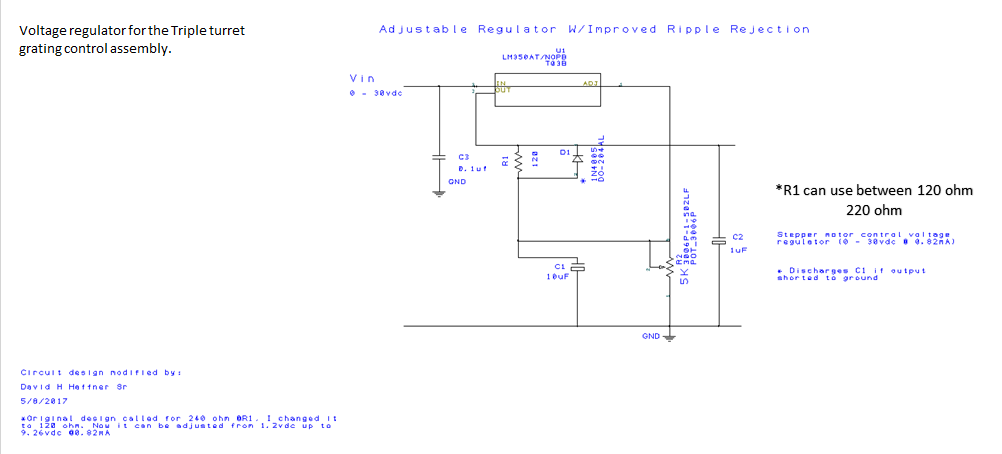
Here is the schematic for the LM350T voltage regulator;
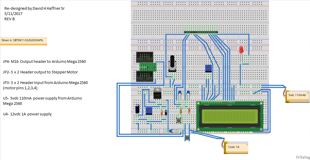
Next is an Arduino barebones breadboard layout;
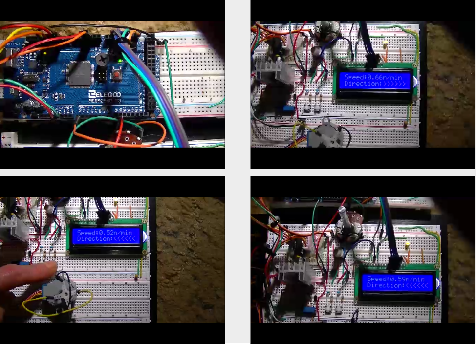
A 4 panel snapshot view;
Discussions
Become a Hackaday.io Member
Create an account to leave a comment. Already have an account? Log In.
Cool! Would you be willing to share the debounce function you wrote? I might need to debounce a breakbeam that I'm working on.
Are you sure? yes | no
Hey Muriel, sure thing. 1st off though you really need the two 0.1uf caps and the 10k resistors at ground, because it eliminates any spikes from in-rush current at switch press (that's the hardware part,) now the software part;
//Variables will change
int ledState = HIGH; //current state of the output pin
int buttonState; //current reading from the input pin
int lastButtonState = LOW; //the previous reading from the input pin
unsigned long lastDebounceTime = 0;
unsigned long debounceDelay = 50;
void loop() {
//read the state of the switch into local variable
int reading = digitalRead(button_1);/*Name U defined as "button"*/
int reading = digitalRead(button_2);
// check to see if U pressed the button
//(i.e Input went from LOW to HIGH)
// if switch changed, due to noise or pressing:
if (reading != lastButtonState) {
// reset the debouncing timer
lastDebounceTime = millis();
}
if ((millis() - lastDebounceTime) > debounceDelay) {
//whatever the reading is at, it's been there for longer
// than the debounce delay, so take it as the actual current state:
// if the button state has changed:
if (reading != buttonState) {
buttonState = reading;
// only toggle the LED if the new button state is HIGH
if (buttonState == HIGH) {
ledState = !ledState;
Here is the entire code:
/*The circuit and code modified by me on 5/15/2017
David H Haffner Sr as part of my prototype triple
turret grating assembly, for my project 3D-Printable Raman Spectrometer
http://hackaday.io/project/18126-3d-printable-raman-spectrometer
The circuit as it stands now on a Mega 2560:
LCD RS pin to digital pin 8
LCD Enable pin to digital pin 9
LCD D4 pin to digital pin 7
LCD D5 pin to digital pin 6
LCD D6 pin to digital pin 5
LCD D7 pin to digital pin 4
LCD R/W pin to ground
LCD VSS pin to ground
LCD VCC pin to 5V
10K resistor:Trimmer POT
ends to +5V and ground
wiper to LCD VO pin (pin 3)
Library originally added 18 Apr 2008
by David A. Mellis
library modified 5 Jul 2009
by Limor Fried (http://www.ladyada.net)
example added 9 Jul 2009
by Tom Igoe
modified 22 Nov 2010
by Tom Igoe
This example code is in the public domain.
http://www.arduino.cc/en/Tutorial/LiquidCrystal
*/
// include the library code:
#include
#include
#include
const int button_1 = 1;// variable for storing button's status(this is for my referene :))
const int button_2 = 0;// variable for storing button's status
const int ledPin = 13;
const int motorPin1 = 12;// IN1 on motor control board
const int motorPin2 = 11;// IN2
const int motorPin3 = 10;// IN3
const int motorPin4 = 9; // IN4
//Variables will change
int ledState = HIGH; //current state of the output pin
int buttonState; //current reading from the input pin
int lastButtonState = LOW; //the previous reading from the input pin
unsigned long lastDebounceTime = 0;
unsigned long debounceDelay = 50;
int val1 = 0;
int val2 = 0;
// initialize the library with the numbers of the interface pins
LiquidCrystal lcd(21, 20, 19, 18, 17, 16);
const int stepsPerRevolution = 200;
// Here set the stepper motor rotation step how much is a circle
int dim = stepsPerRevolution;
// Set the step motor number and pin
Stepper myStepper(stepsPerRevolution, 13, 12, 11, 10);
void setup() {
pinMode(3, INPUT_PULLUP);//Sets the buttons as input
pinMode(ledPin, OUTPUT);
pinMode(2, INPUT_PULLUP);
pinMode(ledPin, OUTPUT);
//set initial LED state
digitalWrite(ledPin, ledState);
attachInterrupt(1, counterclockwise, FALLING);
attachInterrupt(0, clockwise, FALLING);
// set up the LCD's number of columns and rows:
lcd.begin(16, 2);
// Print a message to the LCD.
lcd.print("Speed:");
lcd.setCursor(10, 0);
lcd.print("n/min");
lcd.setCursor(0, 1);
lcd.print("Direction:");
}
void loop() {
//read the state of the switch into local variable
int reading = digitalRead(button_1);
int redaing = digitalRead(button_2);
// check to see if U pressed the button
//(i.e Input went from LOW to HIGH)
// if switch changed, due to noise or pressing:
if (reading != lastButtonState) {
// reset the debouncing timer
lastDebounceTime = millis();
}
if ((millis() - lastDebounceTime) > debounceDelay) {
//whatever the reading is at, it's been there for longer
// than the debounce delay, so take it as the actual current state:
// if the button state has changed:
if (reading != buttonState) {
buttonState = reading;
// only toggle the LED if the new button state is HIGH
if (buttonState == HIGH) {
ledState = !ledState;
}
}
}
myStepper.step(dim);
void Direction();
// Read the sensor values:
int sensorReading = analogRead(A0);
// Map it to a range of 0-150:
int motorSpeed = map(sensorReading, 0, 1023, 0, 150);
// Set the motor speed:
if (motorSpeed > 0)
Serial.begin(115200);
val1 = digitalRead(1);
if (val1 == HIGH)
val2 = digitalRead(0);
if (val2 == HIGH)
{
myStepper.setSpeed(motorSpeed);
lcd.setCursor(6, 0);
lcd.print(float(float(motorSpeed) / float(200)));
}
}
void clockwise()
{
// clockwise rotation
dim = stepsPerRevolution;
lcd.setCursor(10, 1);
lcd.print(">>>>>>");
}
void counterclockwise()
{
// anti-clockwise
dim = -stepsPerRevolution;
lcd.setCursor(10, 1);
lcd.print("<<<<<<");
}
Are you sure? yes | no