 David H Haffner Sr
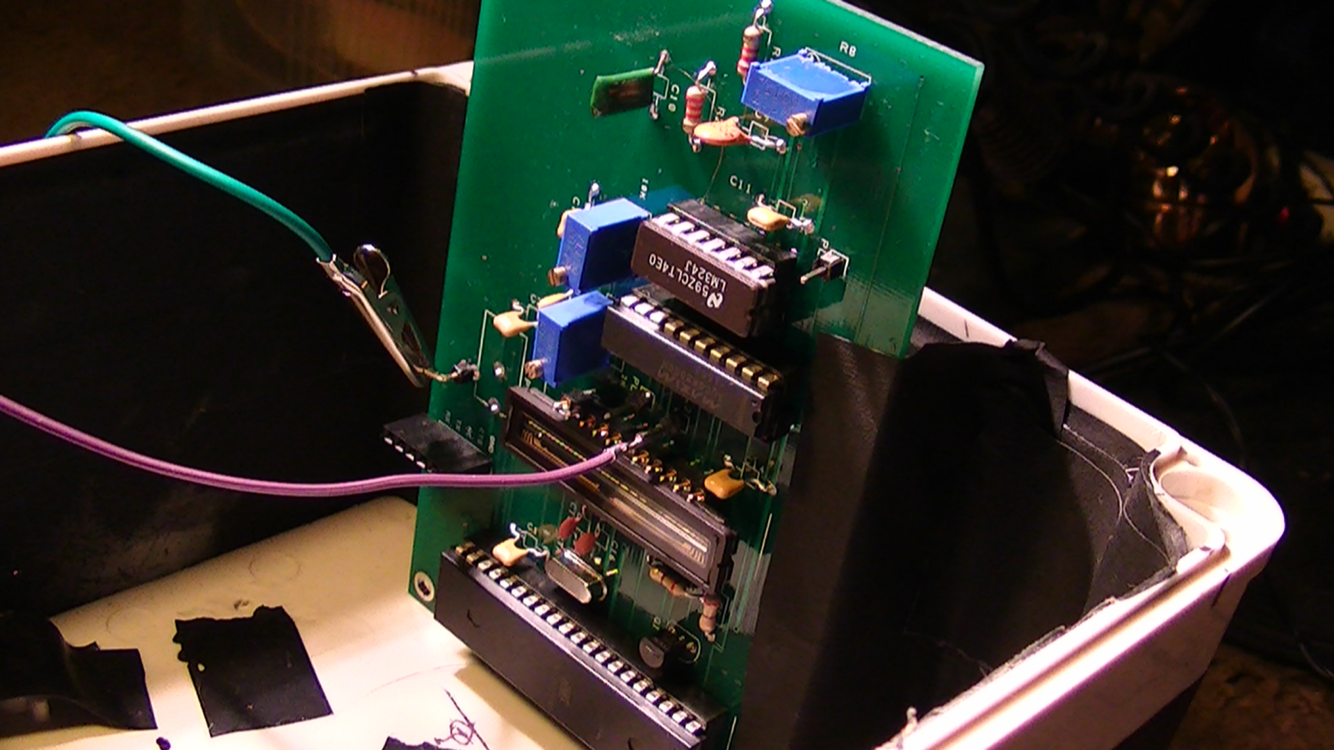
Well, this may be the ugliest test platform I have ever made but it sure worked, I had to modify my circuit board @ R8 going to pin#3 at the opamp [LM324], by running a bypass from the C9 [200pf cap,] to pin#3 @ the LM324, some strange ground problem I can't quite figure out yet from manually placing the components on the PCB design circuit in DesignSpark.
Anyway the bypass works like a champ, I have a very low noise floor [SNR] and a very good signal :) I used a RED 650nm laser pointer as my test spectrum to determine resolution, used NO diffraction grating, only a 0.25mm razor blade slit and my silver coated mirror.
Straight to the point, the data is UN-calibrated, for now, but initial results are beautiful.
Data first...
Figure 1 is the 1st spectral image starting from 1500 - 1726 pixels (X axis,)
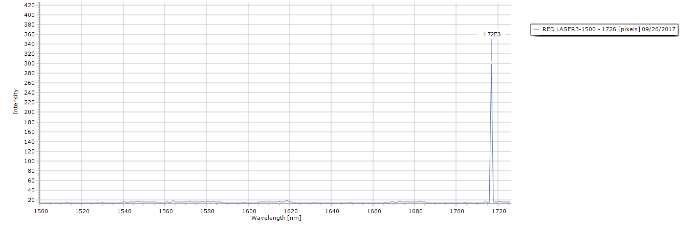
Figure 2 shows the spectrum cutoff @ 1700 - 1726 pixels (X axis,)
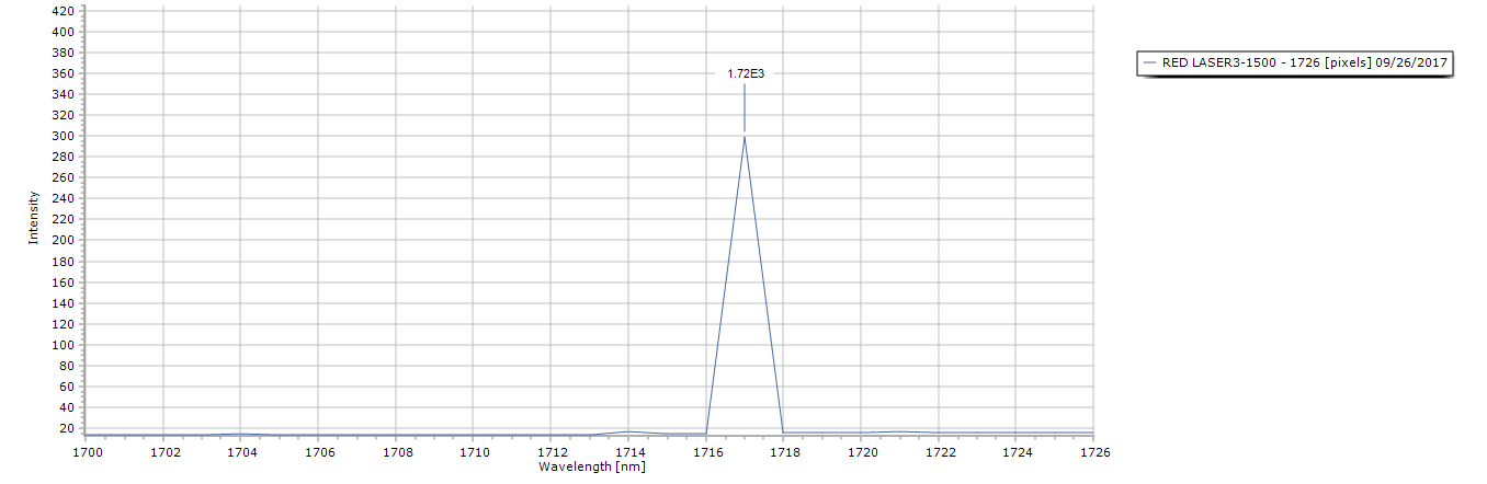 -
-
Next figure (3) is the FWHM data set,

Here we can see peak position @ 1717 pixels (nm) with A Full Width Half Maximum (FWHM) of 1.0547nm, most excellent, especially since I was only using a makeshift entrance slit made from two gillette razor blades @ a width of 0.25mm.
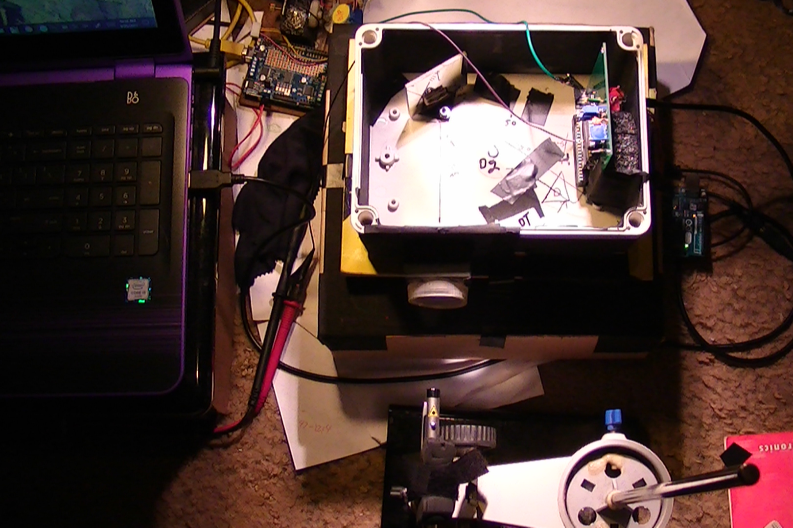
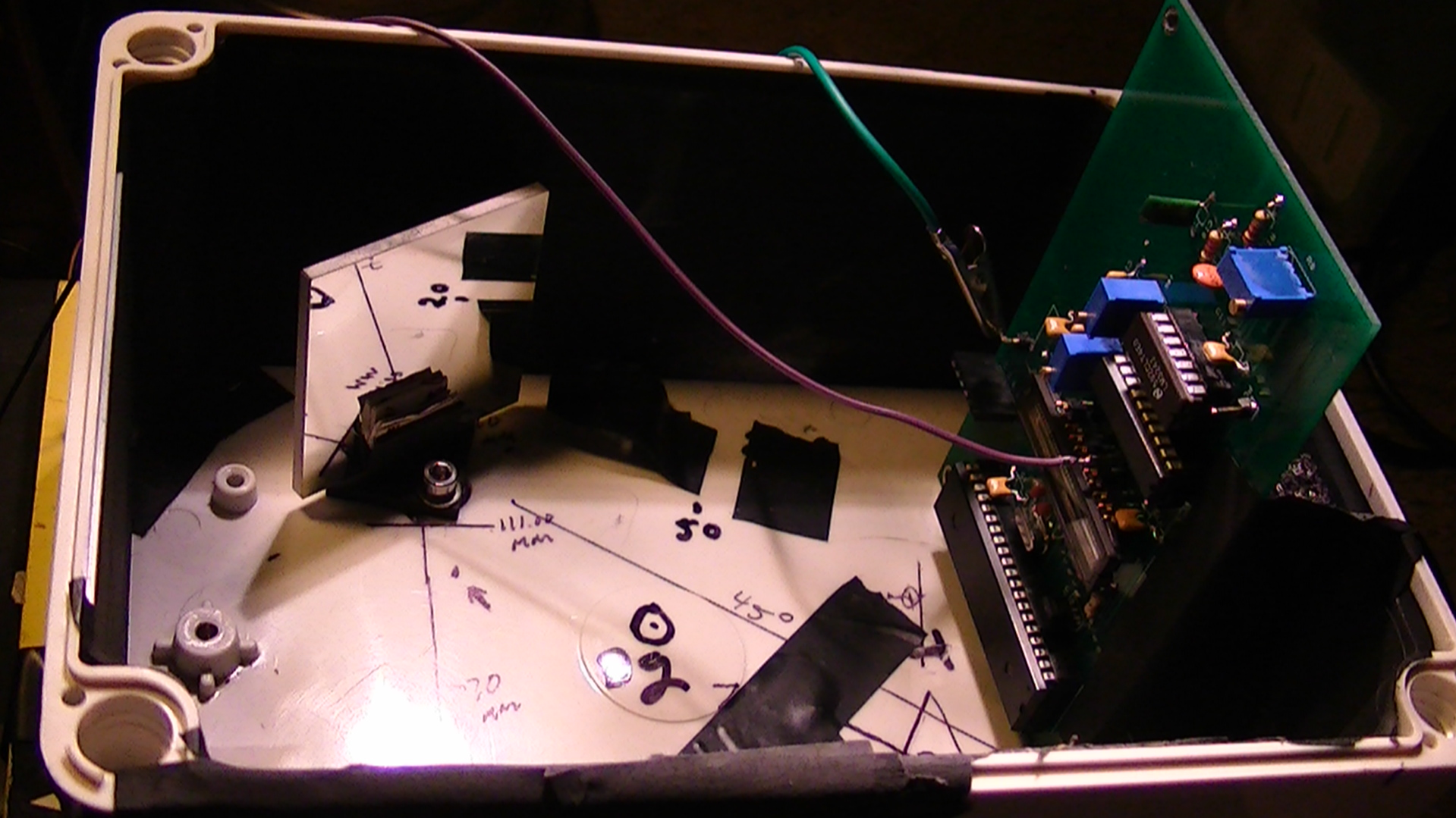
Below is my test platform I made just for this purpose:
Next image is a closer look at the circuit board:

And finally a better look at the angle of the mirror in relation to the detector:
Discussions
Become a Hackaday.io Member
Create an account to leave a comment. Already have an account? Log In.