 Mike Rigsby
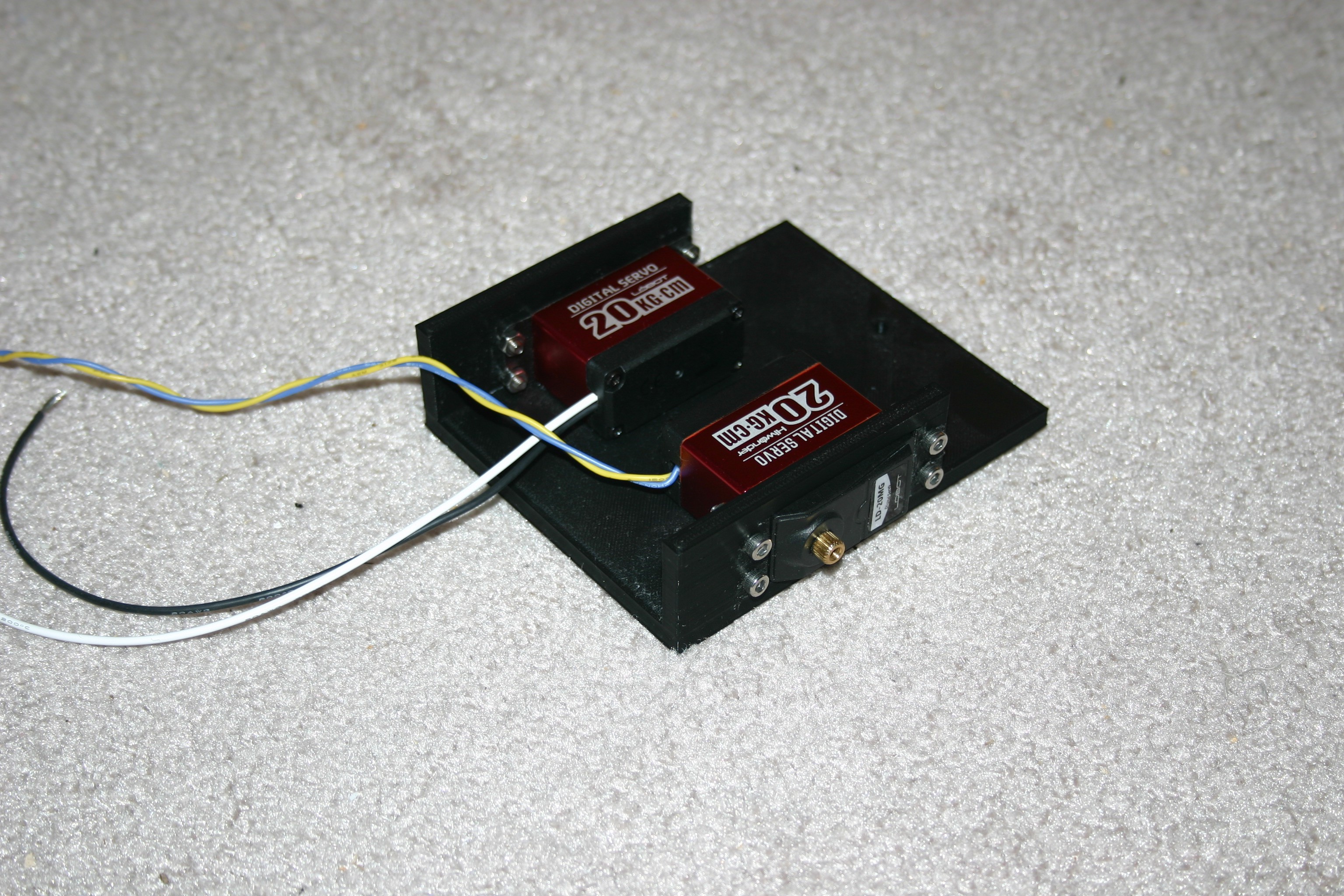
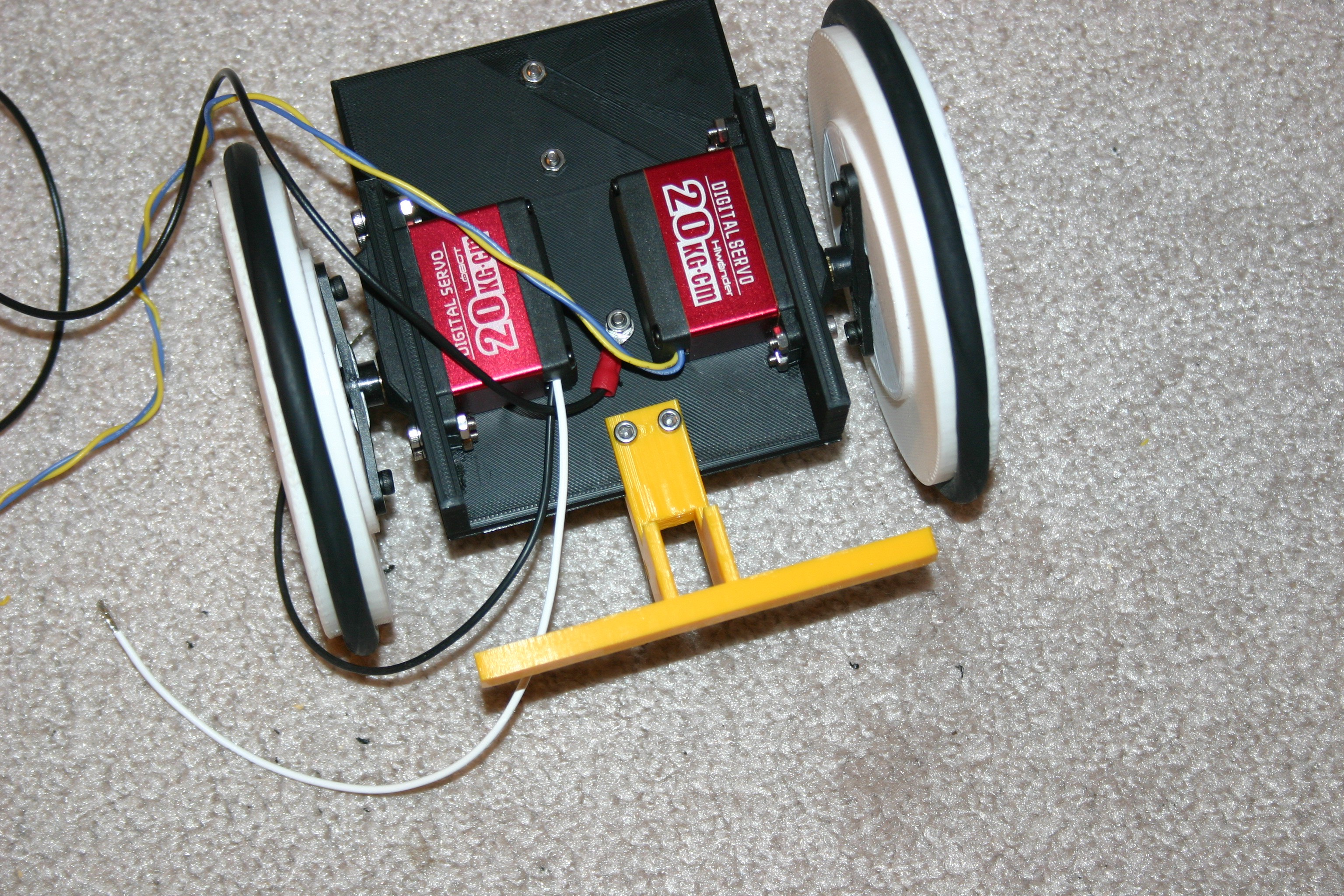
Start with the servo motors--I selected metal gear servos that do not have end stops.
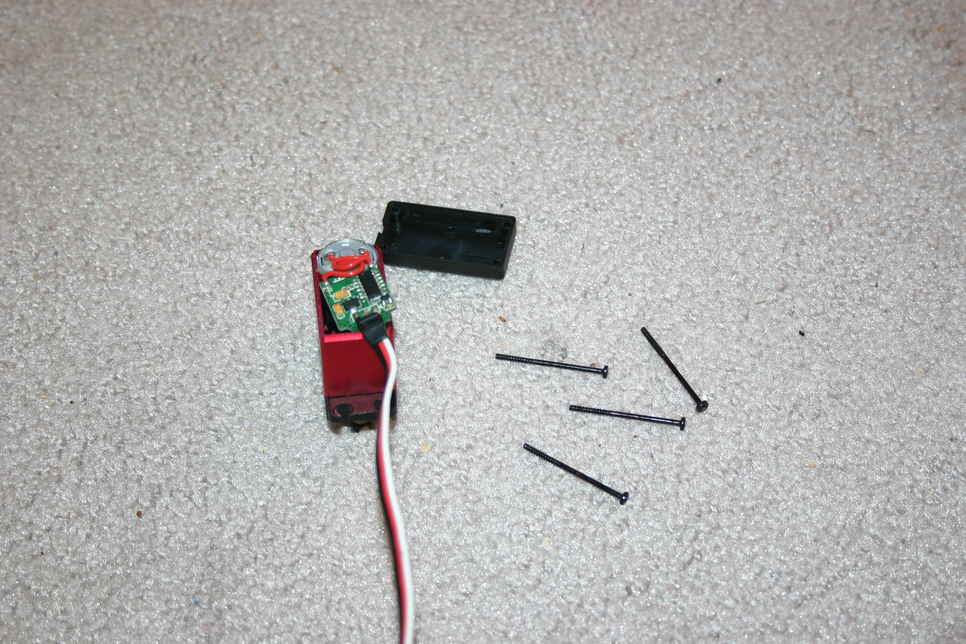
Remove the circuit board.
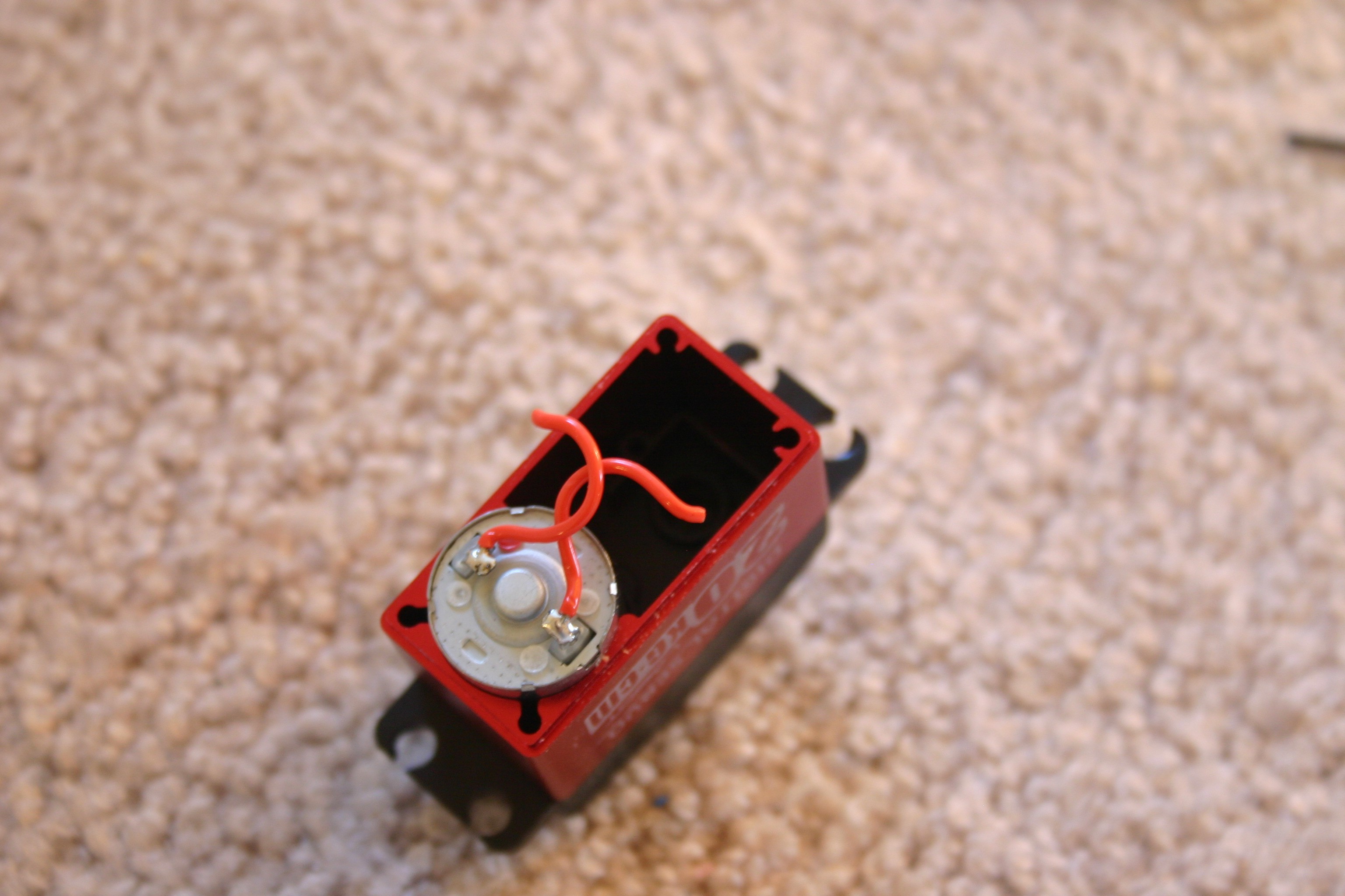
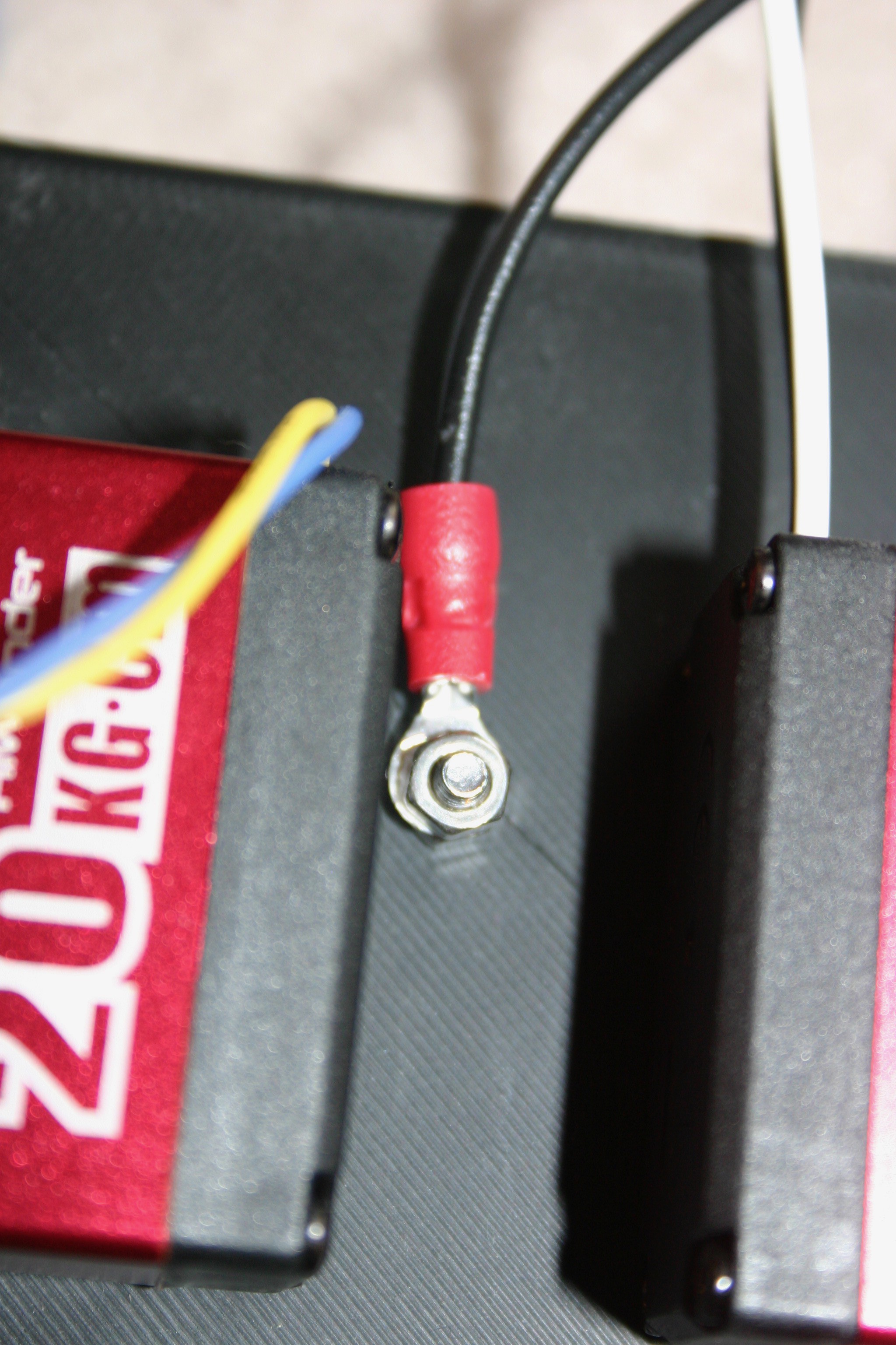
Solder wires to the motor connections.
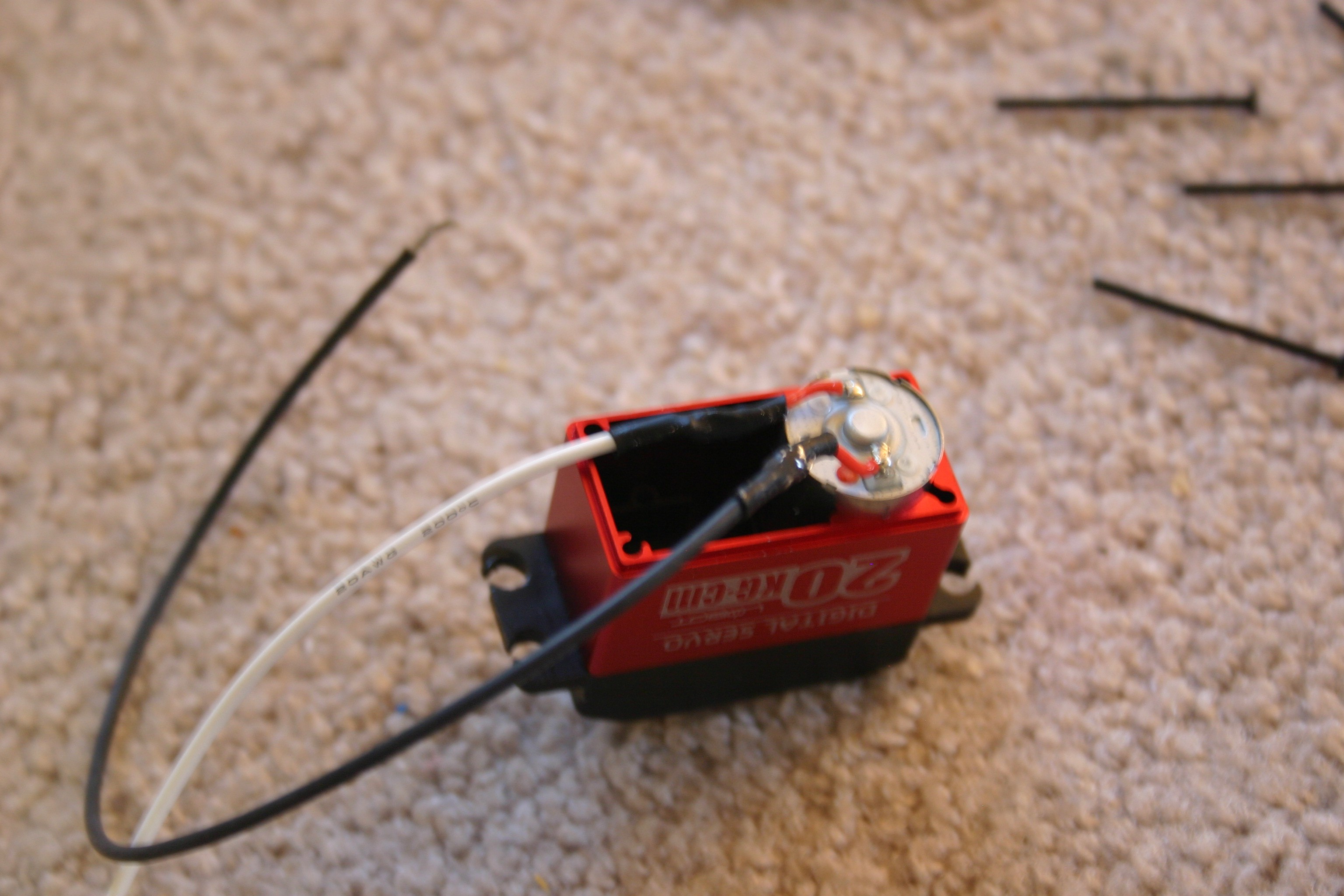
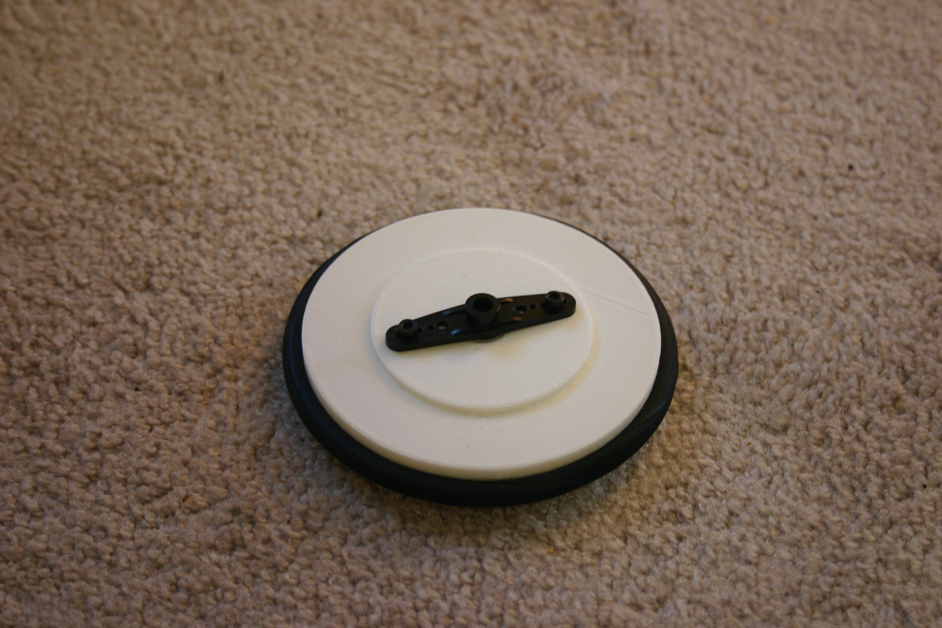
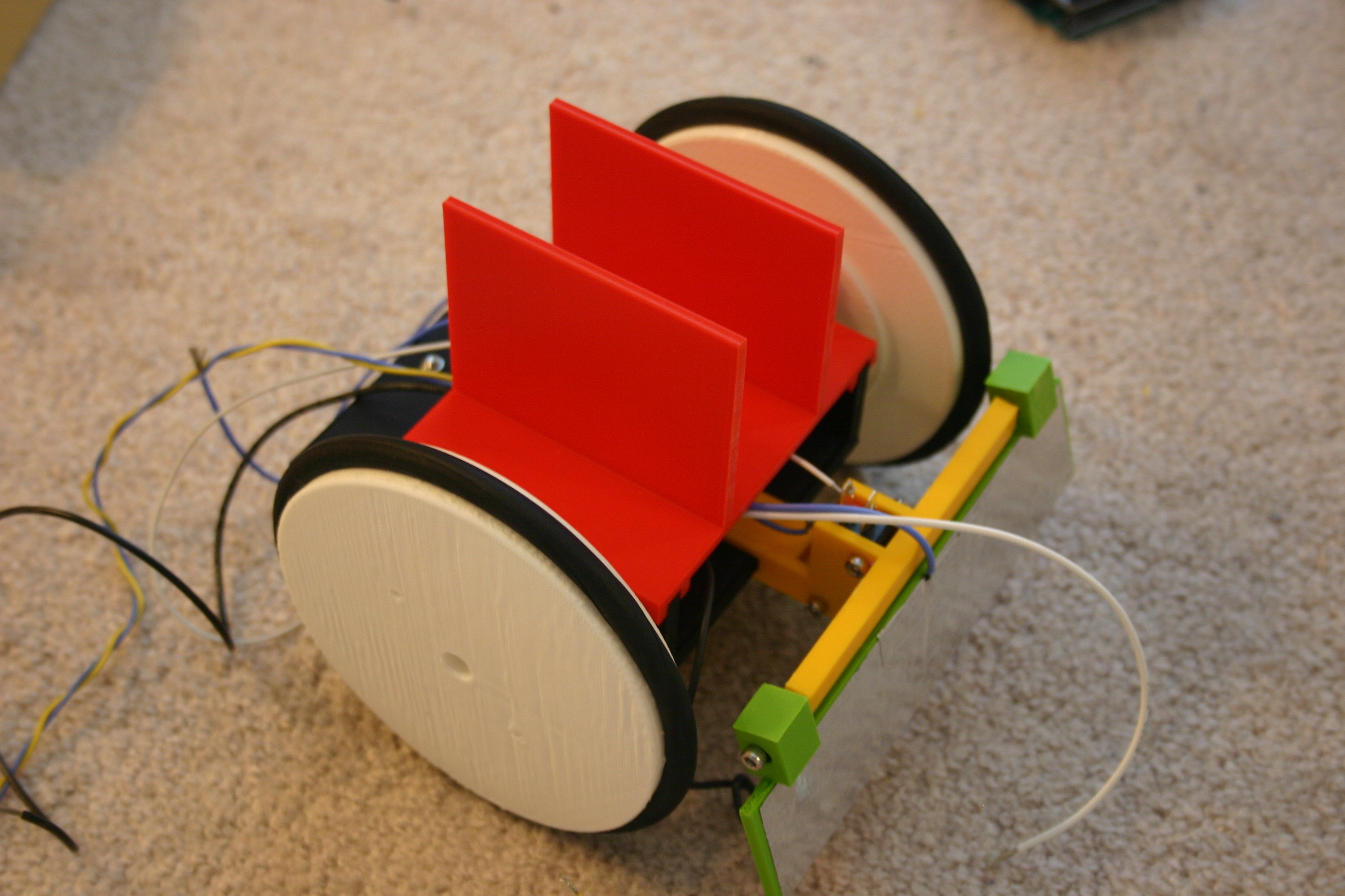
Put the motor back together. Place the vacuum belt (tire) on the wheel.
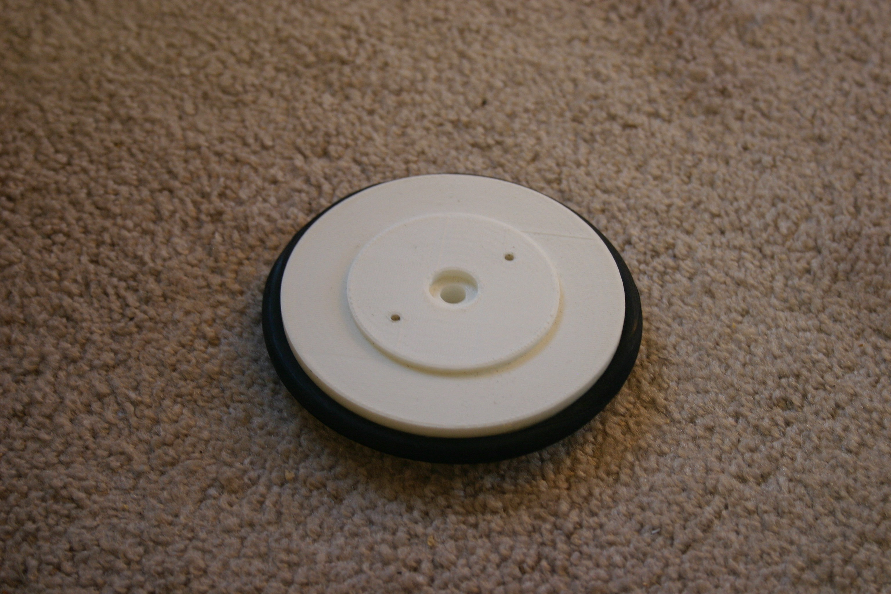
Attach the servo horn to the wheel using 3mm screws.
Install the servo motors.
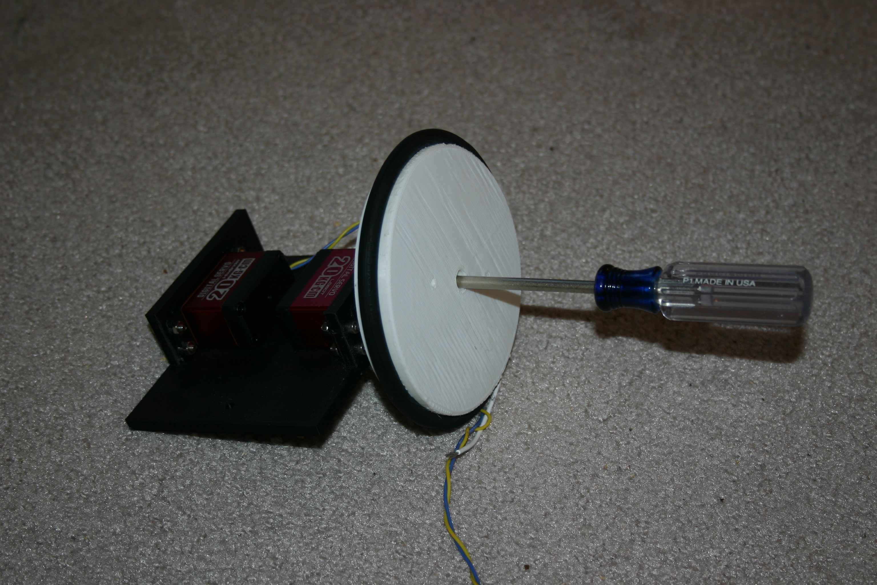
Secure the wheels to the motor shaft.
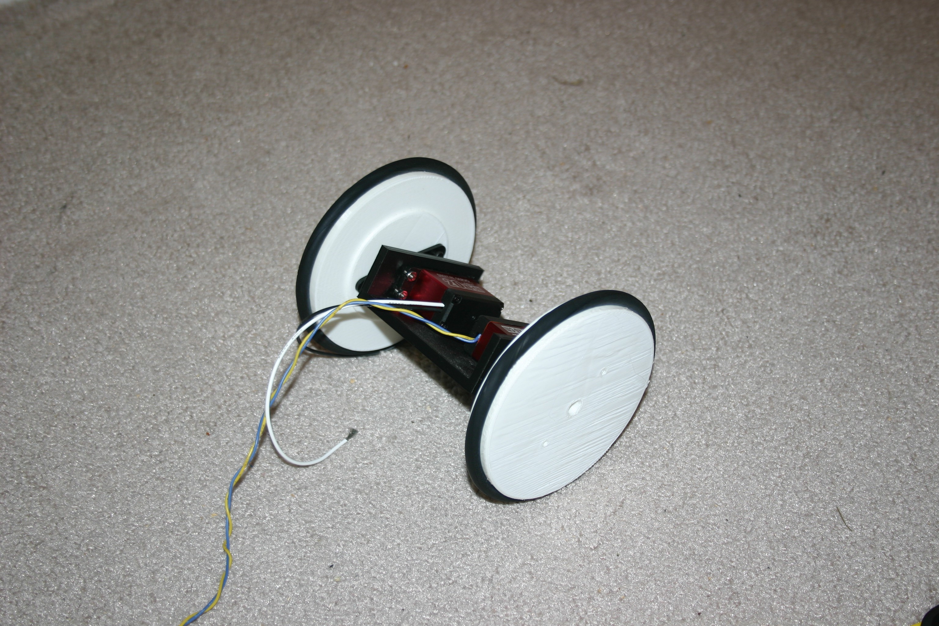
Repeat.
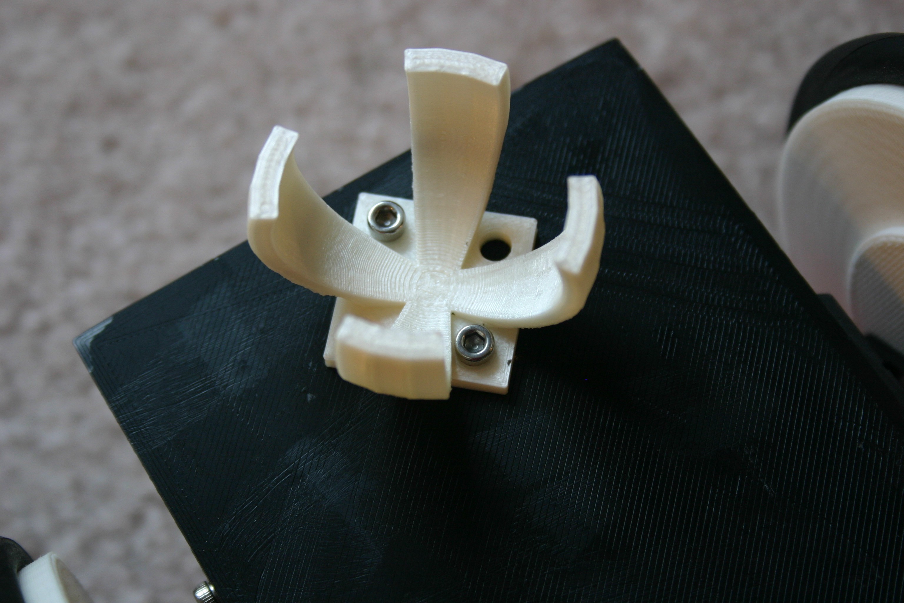
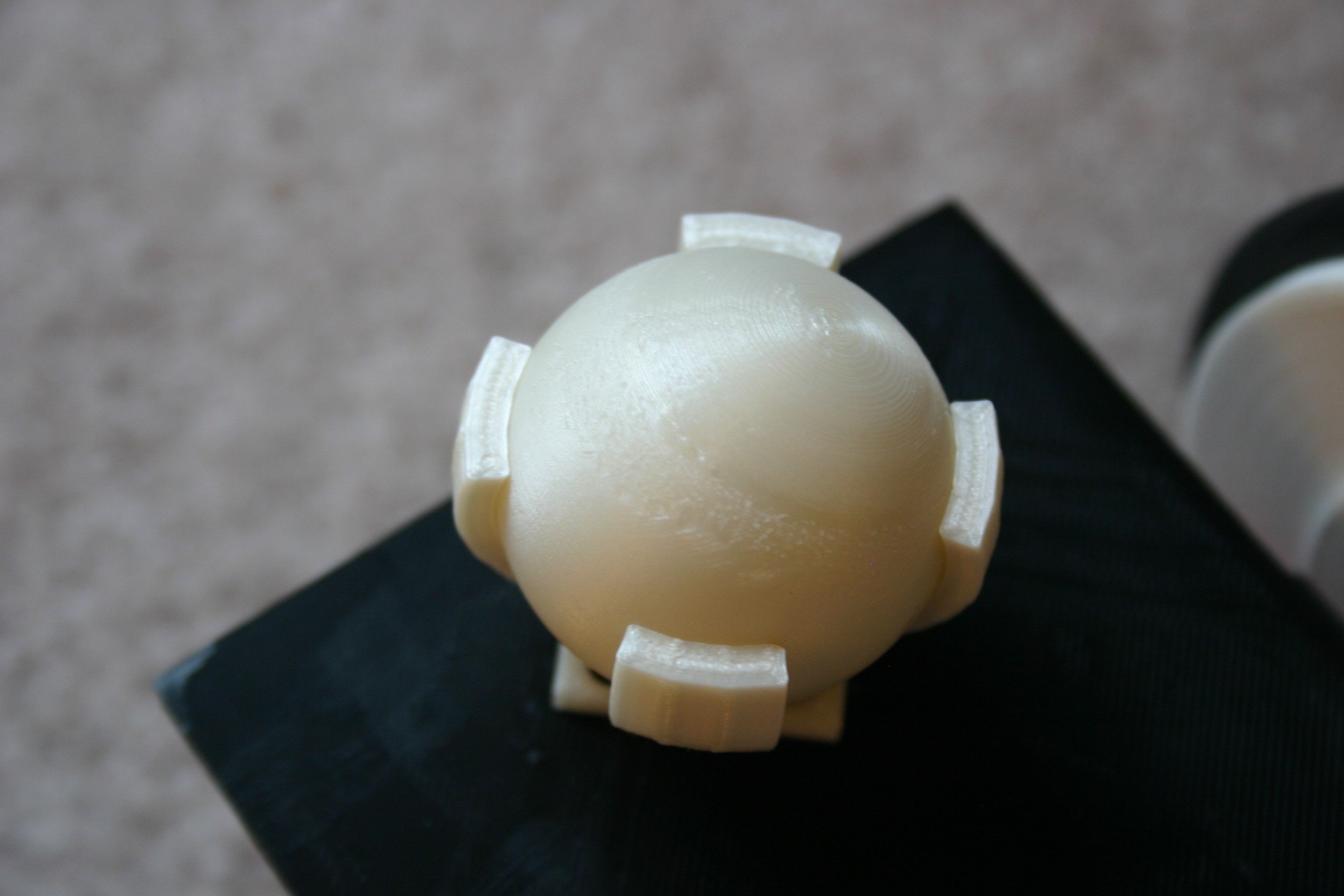
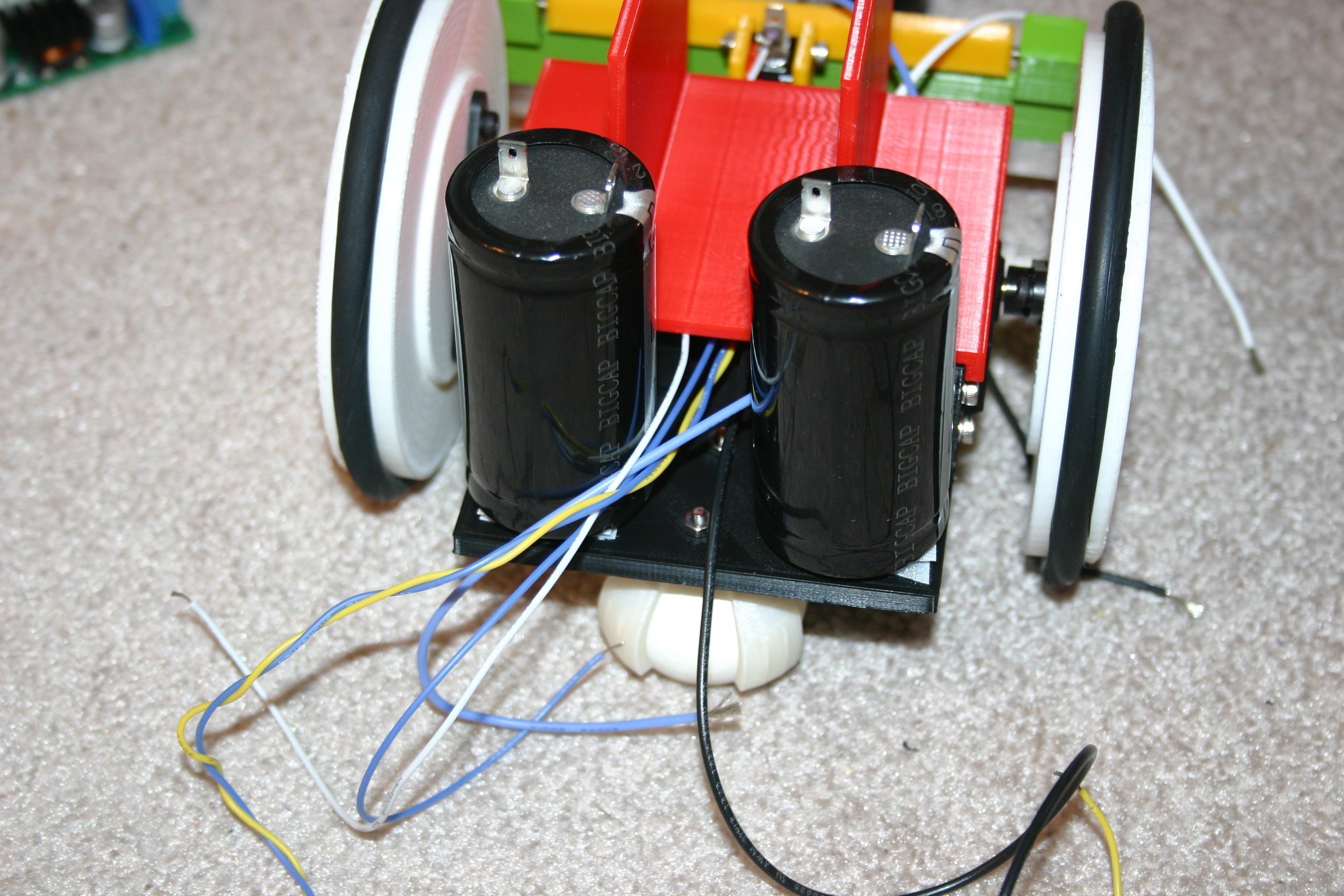
Install the holder for the rear caster ball.
Insert the caster ball.
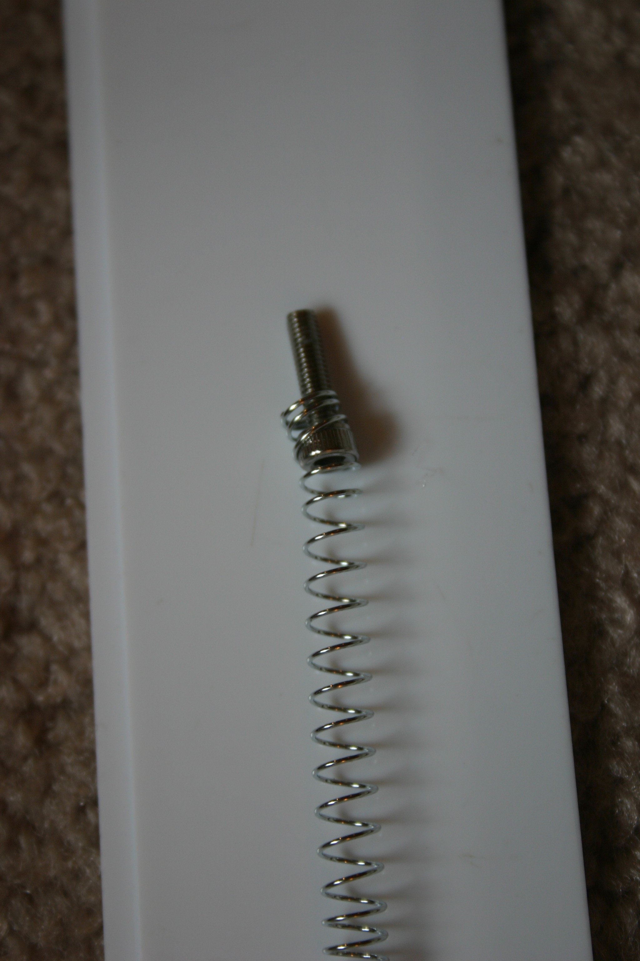
Insert a 3mm screw into one end of the spring.
Drill a hole in the base and put the screw through the hole.
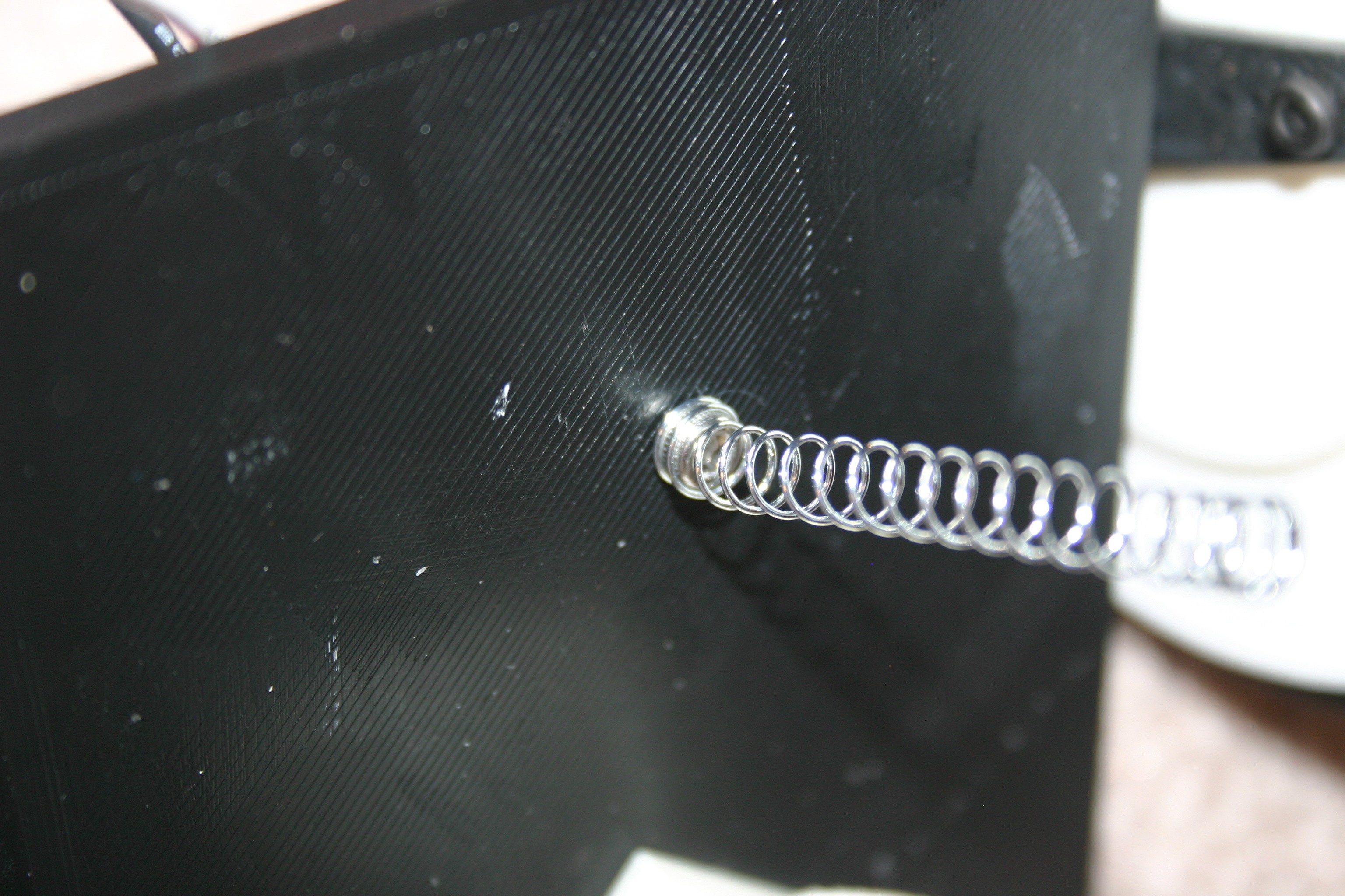
On the other side of the base attach the pickup wire.
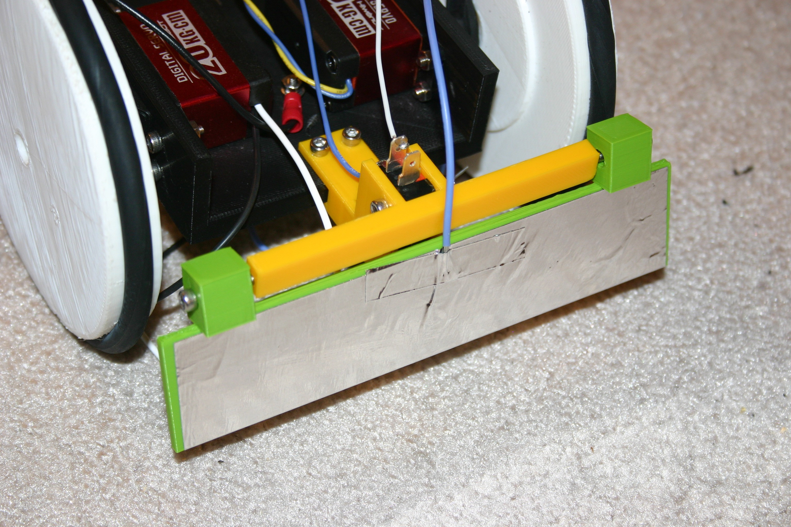
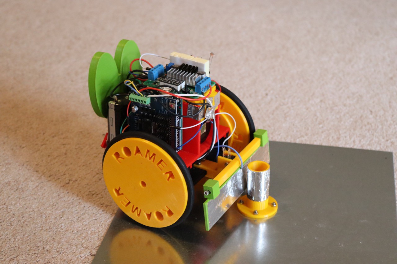
Secure the switch holder to the front of the frame.
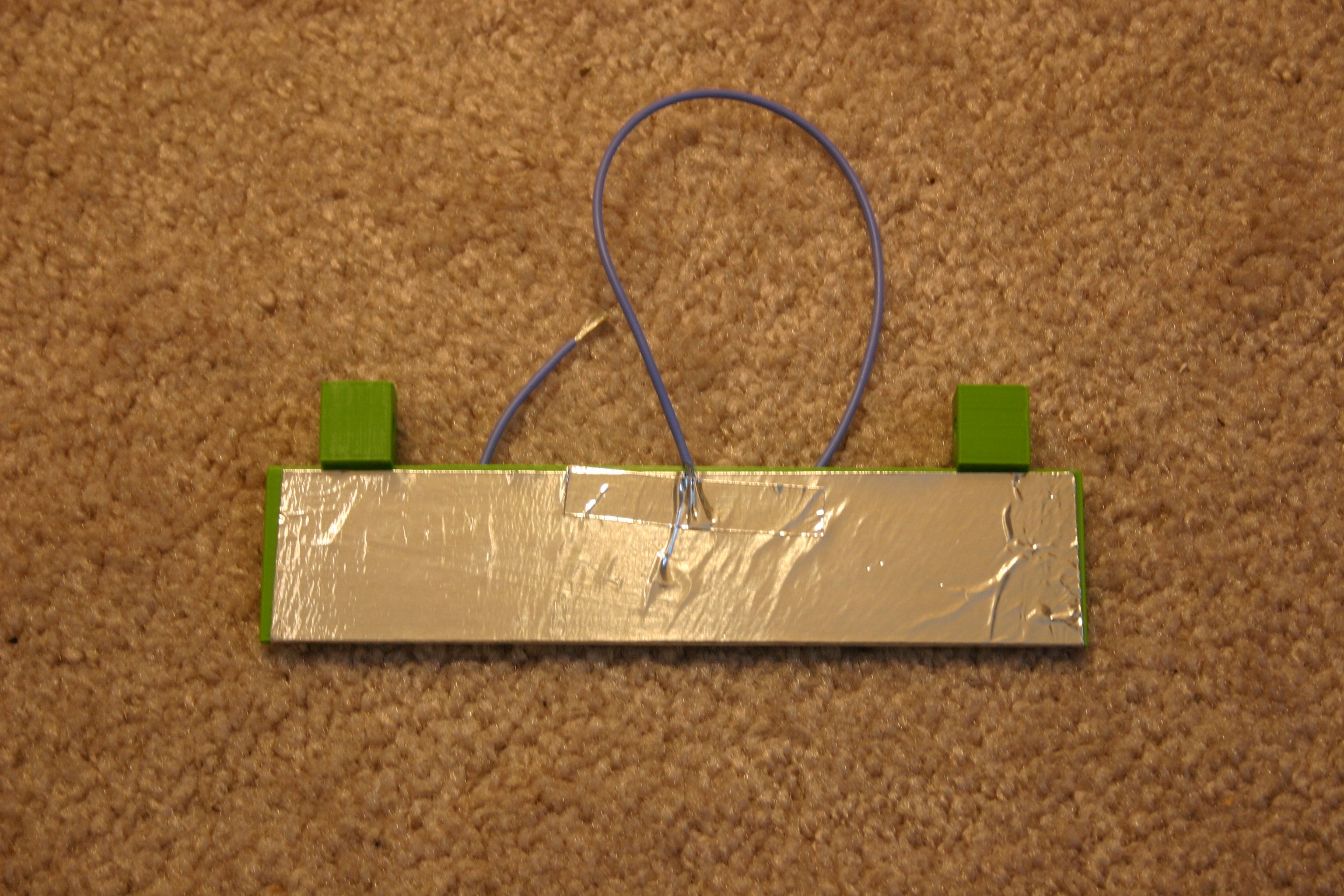
Attach aluminum duct tape to the front bumper. Tape a wire (so that it connects to the foil electrically) to the bumper.
Install a lever switch in the switch holder.
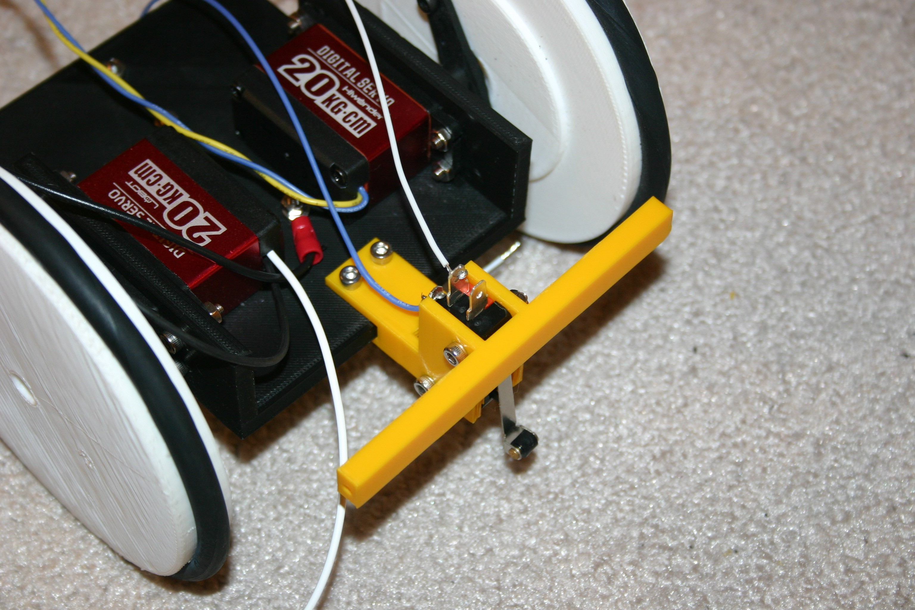
Attach the bumper to the switch holder using 3mm screws.
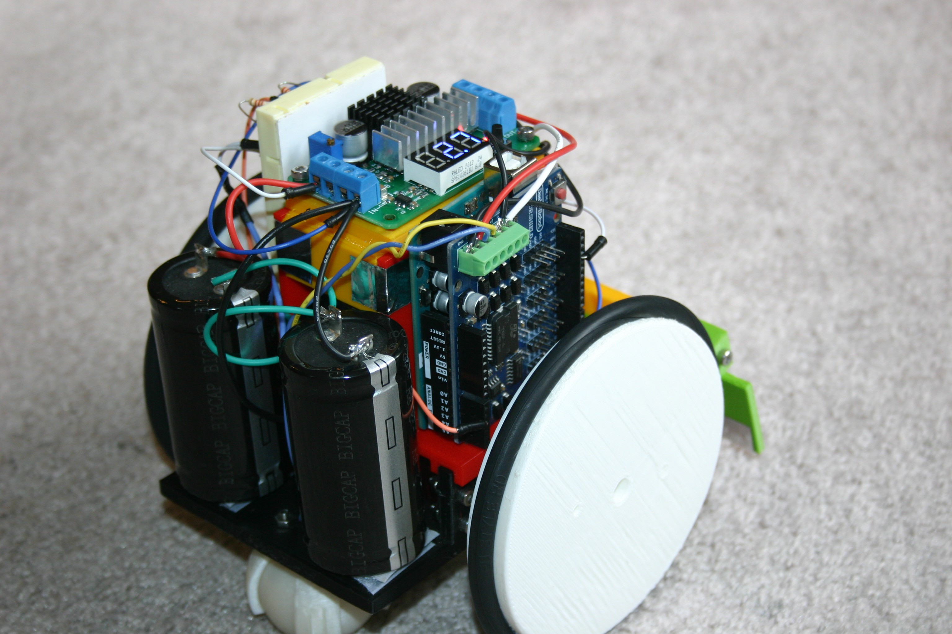
Place the board/capacitor holder onto the frame. Glue together (or lightly melt using a soldering iron).
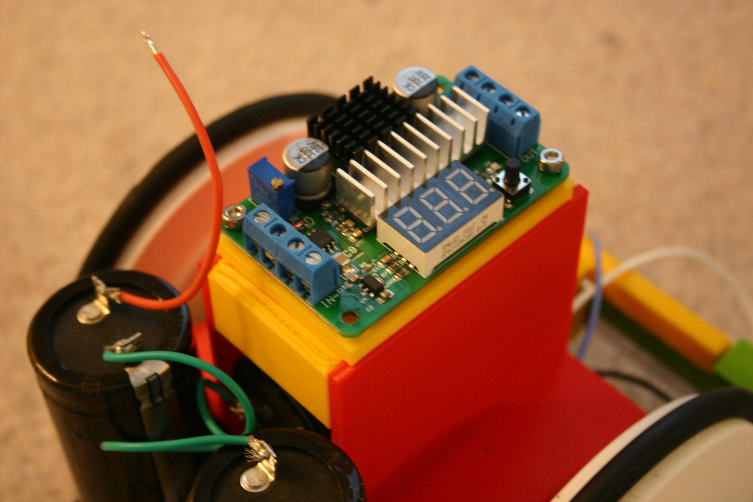
Attach two capacitors to the rear part of the frame using Velcro strips.
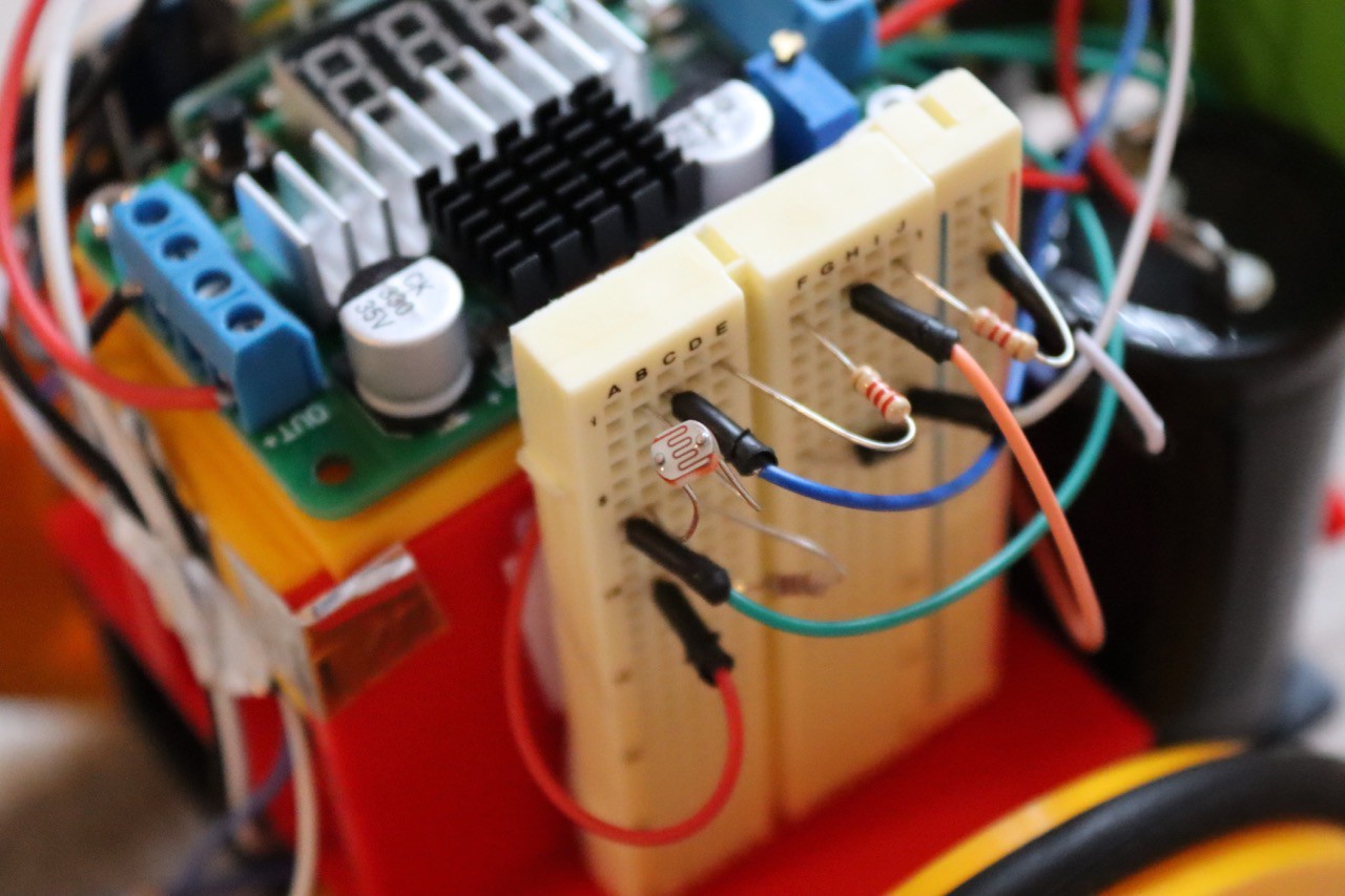
Place the boost converter on the electronics holder.
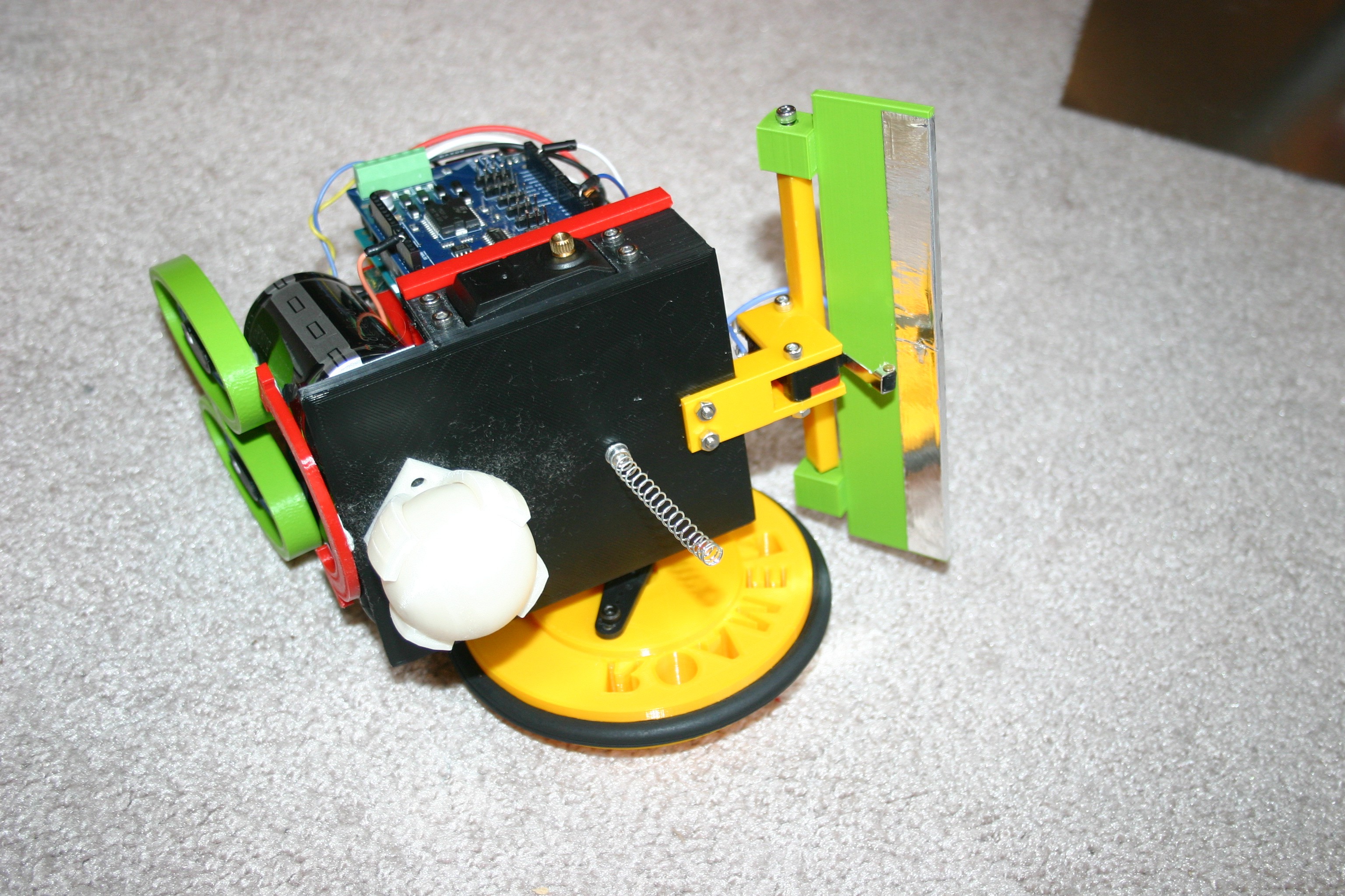
Secure the charge plate pole to the charge base using 3mm screws.
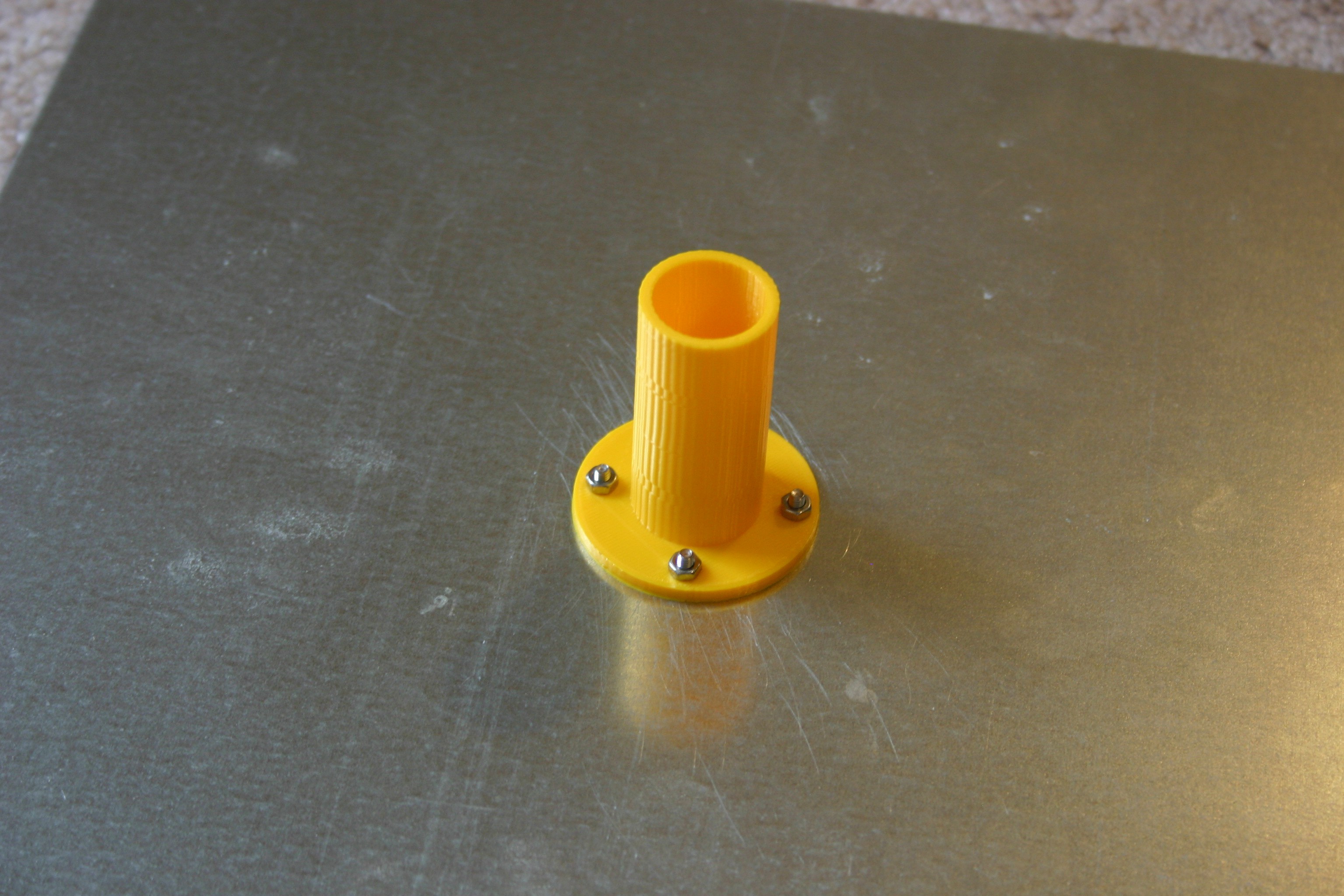
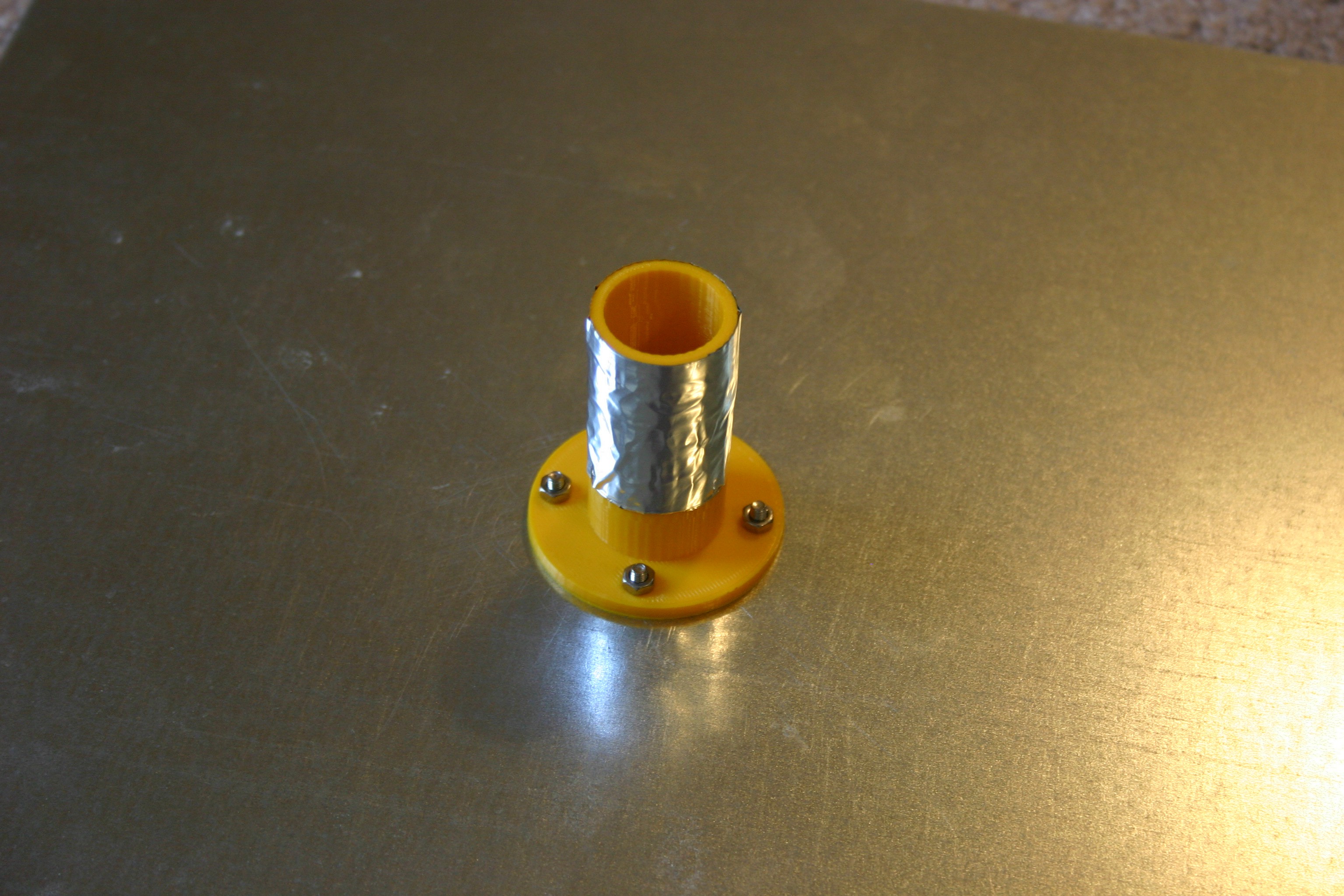
Place foil tape on the pole--not touching the base.
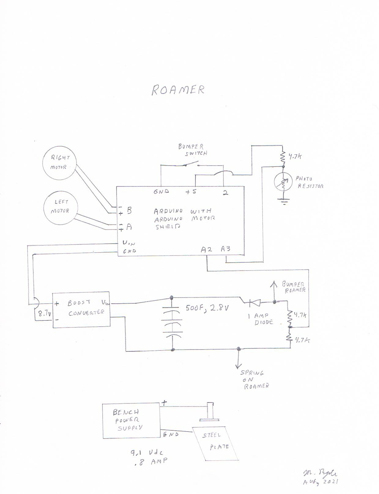
Add the breadboard and wire according to the schematic.
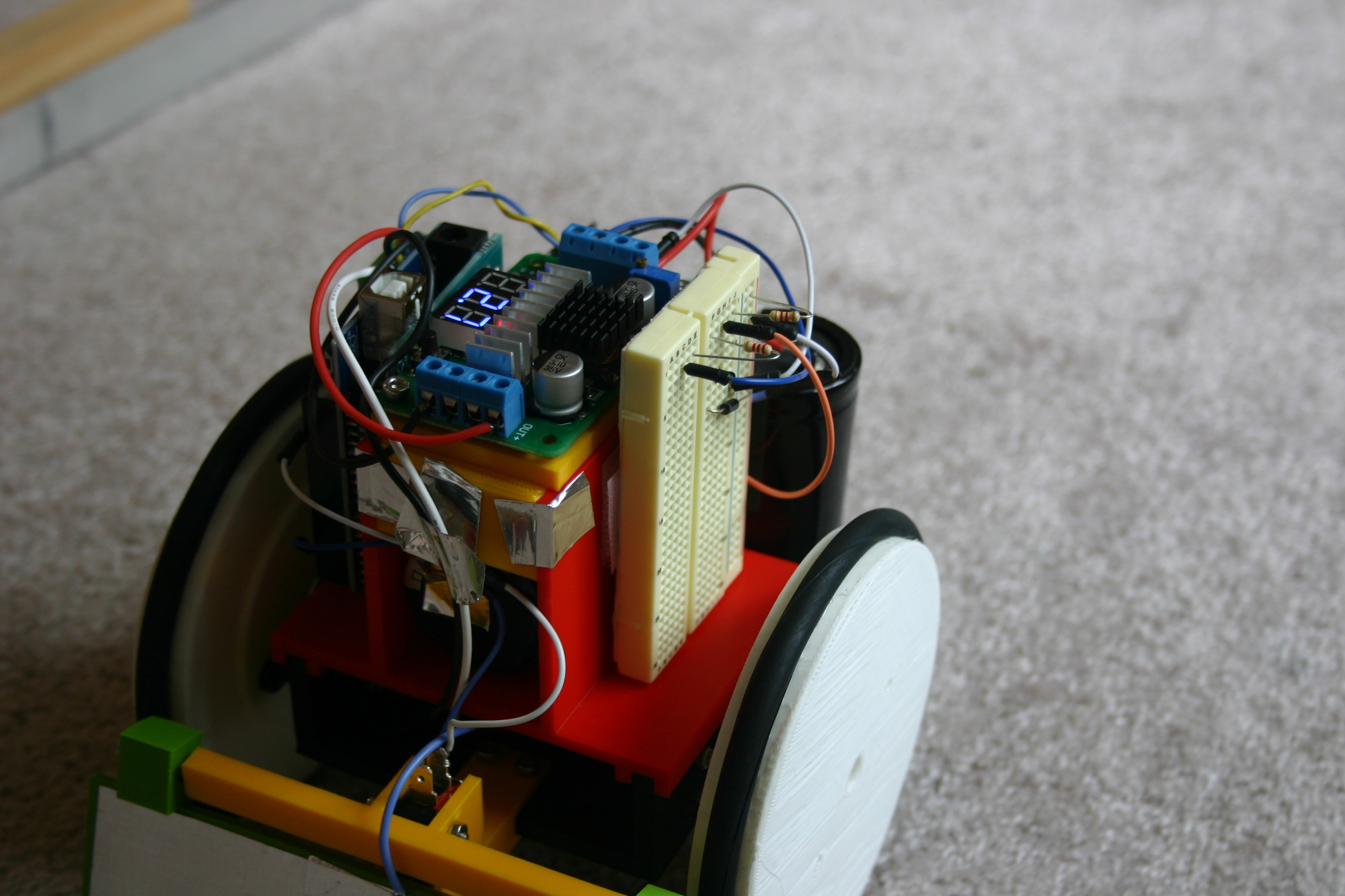
Add the Arduino and motor shield. Secure using Velcro.
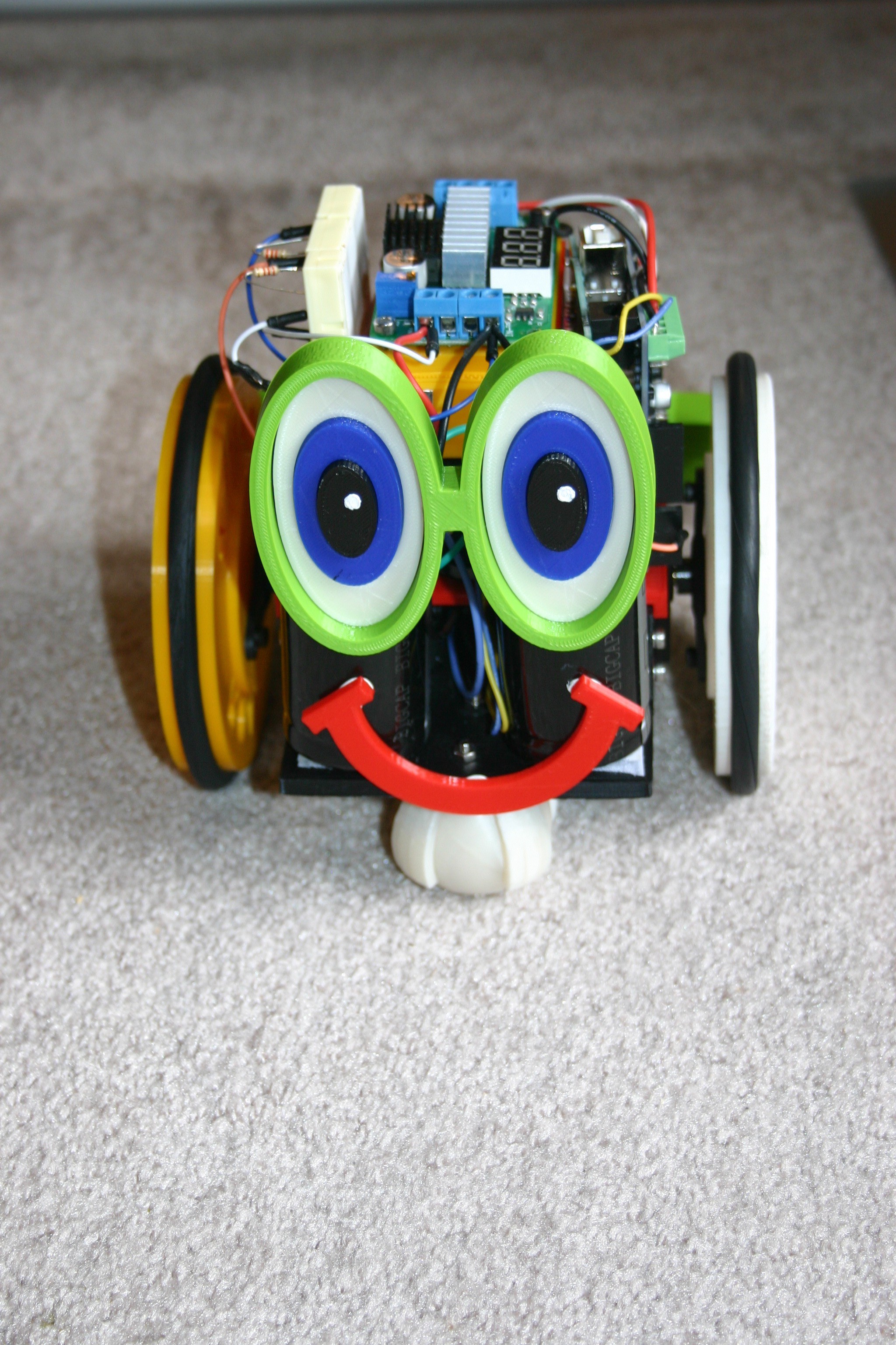
Add the eyes and smile to the back.
The spring and the bumper are the contact points for charging. The bumper should receive positive voltage from the power supply and the spring receives negative.
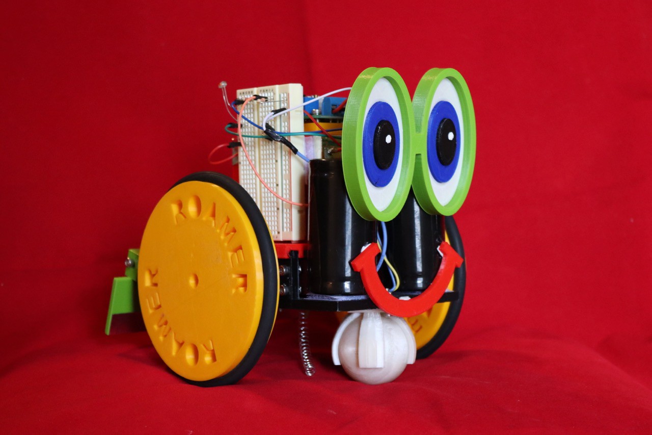
The photocell enables Roamer to "know" that it is dark--then remain on the charger until morning.
Discussions
Become a Hackaday.io Member
Create an account to leave a comment. Already have an account? Log In.