 Guillermo Perez Guillen
This is a nice project and I have updated it. Below you can see the particular goals:
- Developing a reflector to concentrate the energy of UV lamp on an object: backless stool;
- Making the Cascade Classifier of a backless stool u other object; and
- Using of OpenCV on the Autonomous Robot to locate the correct position of the backless stool, and aim the reflector on this object.
Notes:
- It's important to clarify that in this new version, the autonomous robot doesn't move and only aims the UV radiation on the desired target when we give it the voice command.
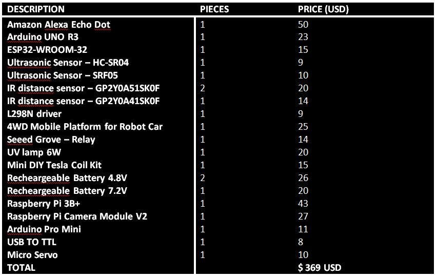
- As we did in first version of this project, now the estimated price of the hardware components is approx $ 369 USD.
UV Reflector
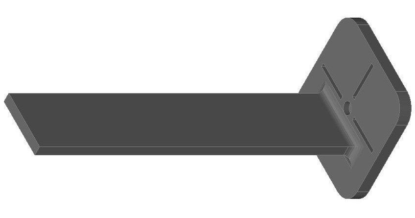
We will print several parts that will be used to assemble UV Reflector with the "4WD Robot Car" chassis. In the figure below I show you the image of UV Reflector holder - part 1.

And the UV Reflector holder - part 2.
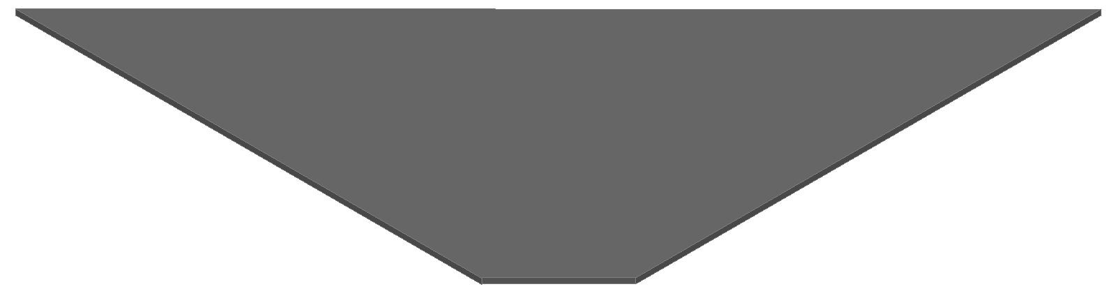
Below I show you the piece that helped me to make the UV reflector (you must print 4 pieces and cover them with aluminum foil).
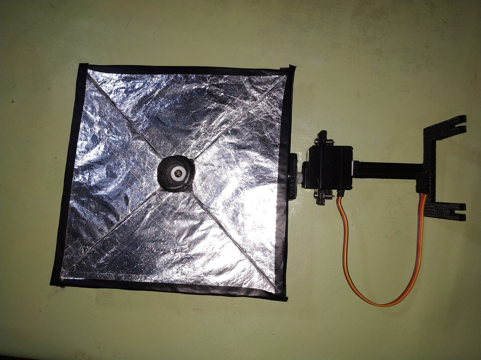
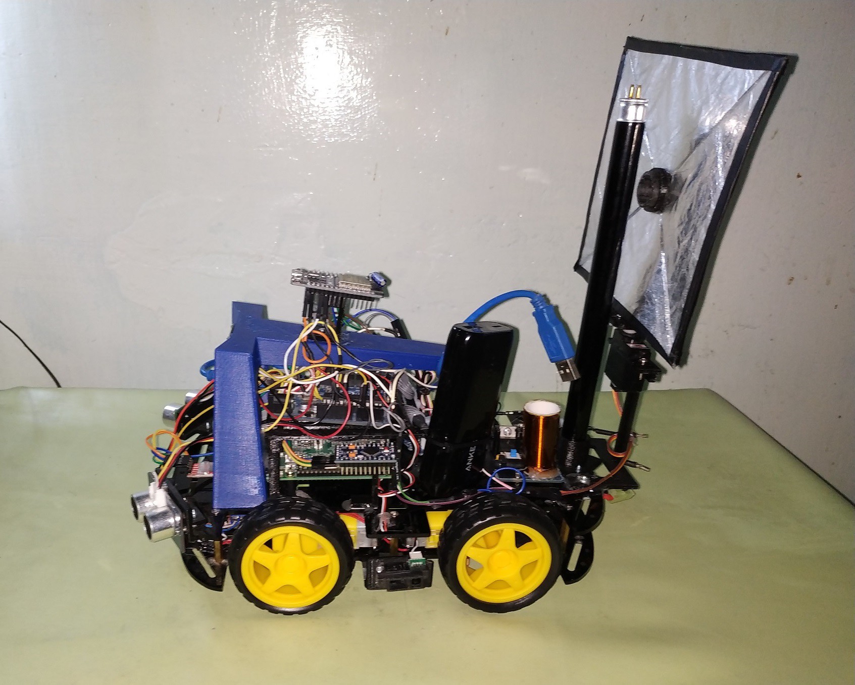
Below, I show you all the assembled parts. Note: Fix the servo as shown in the picture.
Finally, below I show you how to mount the UV reflector on the chassis of the autonomous robot.
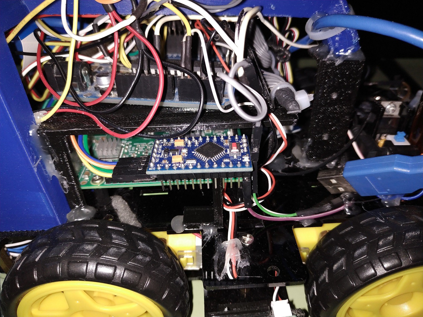
Close-up of the image where we can see the Arduino Pro Mini board
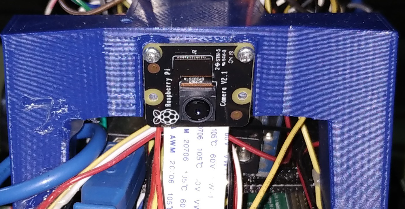
Mounting the Raspberry Pi camera.
A view from the opposite side we can see the Raspberry Pi board.

OpenCV
A nice tutorial for installing OpenCV on my Raspberry Pi is: https://pimylifeup.com/raspberry-pi-opencv/
The steps to make the classifier are shown below:
- A --> Collecting Image Database
- B --> Arranging Negative Images
- C --> Crop & Mark Positive Images
- D --> Creating a vector of positive images
- E --> Haar-Training
- F --> Creating the XML File
Notes:
- In the next tutorial you can find detailed information and learn how to work with these steps: https://www.hackster.io/guillengap/deep-learning-covid-19-detection-with-opencv-d654ef
- I made the training of the cascade classifier: backless_stool.XML and you can get it in my Github code repository: uv-sanitizing-autonomous-robot
Schematic Diagram
Now, we must assemble our schematic diagram as shown in the figure below.

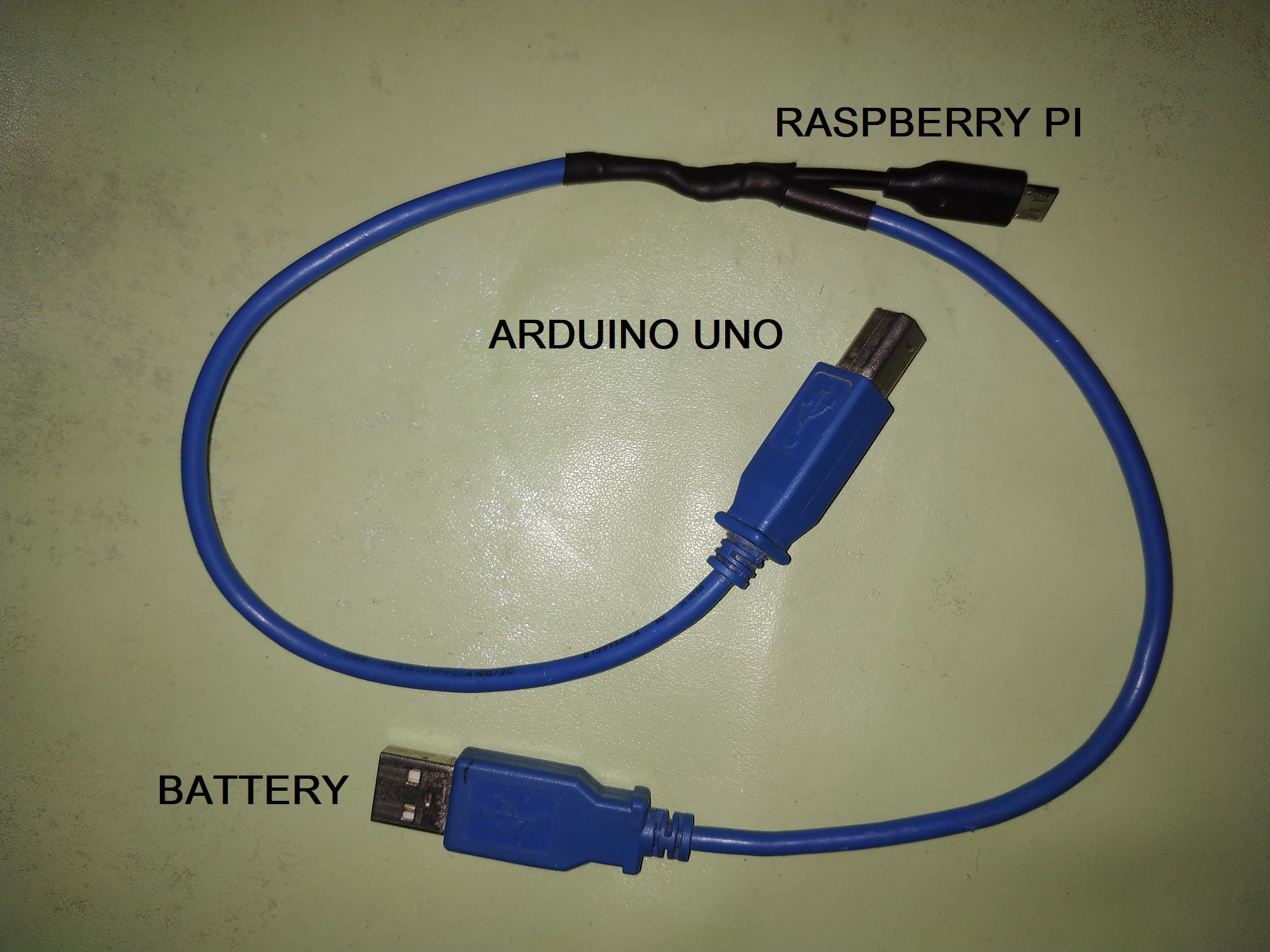
I also made my own cable for connections between Raspberry Pi, Arduino board and the battery:
Codes:
On my Raspberry Pi board, I must run the next code: uv_autonomous_robot.py
# AUTHOR: GUILLERMO PEREZ GUILLEN
# import the necessary packages
from picamera
import time
import cv2
import structural
a=0
b=0
x1=0
y1=0
ser = serial.Serial('/dev/ttyUSB0',9600)

#Load a cascade file for detecting faces
backless_stool_cascade = cv2.CascadeClassifier('backless_stool.xml')

# allow the camera to warmup
time.sleep(0.1)
count = 0

# capture frames from the camera
for frame in camera.capture_continuous(rawCapture, format="bgr", use_video_port=True):
        image = frame.array
        gray = cv2.cvtColor(image, cv2.COLOR_BGR2GRAY)
        backless_stool = backless_stool_cascade.detectMultiScale(gray, 1.3, 5)
        for (x,y,w,h) in backless_stool:
                a=int((2*x+w)/2)
                b=int((2*y+h)/2)
                x1=int(a/3.66)
                y1=int(b/2.55)
                ser.write(struct.pack('>BB', x1,y1))
                cv2.rectangle(image, (x,y), (x+w,y+h), (255,0,0), 2)
                count += 1

        # clear the stream in preparation for the next frame
        rawCapture.truncate(0)

        # if the `q` key was pressed, break from the loop
        if key == ord("q"):
                break
This code finds the horizontal and vertical position of the first vertex of the object (backless stool). Then I send the data through the serial port (ttyUSB0) to the Arduino board. On my Arduino Pro Mini board, I must load the next code: arduino_pro_mini.ino
// AUTHOR: GUILLERMO PEREZ GUILLEN

#include <Servo.h>
int data_x = 0;
int data_y = 0;

Servo myservo_x;
Servo myservo_y;// create servo object to control a servo

void setup() {
  Serial.begin(9600);
  myservo_x.attach(9);  // attaches the servo on pin 9 to the servo object
  myservo_y.attach(10);
  myservo_x.write(900);
  myservo_y.write(90);
}

void loop() {
  while (Serial.available() >= 2) {
    for (int i = 0; i < 200; i++) {
      data[i] = Serial.read();
    }

    Serial.println(data[0]);
    Serial.println(data[1]);
  }
}
This code uses only the horizontal coordinate, and by means of a servo connected to pin 9 we move the reflector towards the backless stool.
Test
In the video below I show you the tests. As you can see, the reflector follows the movement of the image of the backless stool. In this way we make sure that it concentrates the ultraviolet radiation on the desired object.
Discussions
Become a Hackaday.io Member
Create an account to leave a comment. Already have an account? Log In.