 Guillermo Perez Guillen
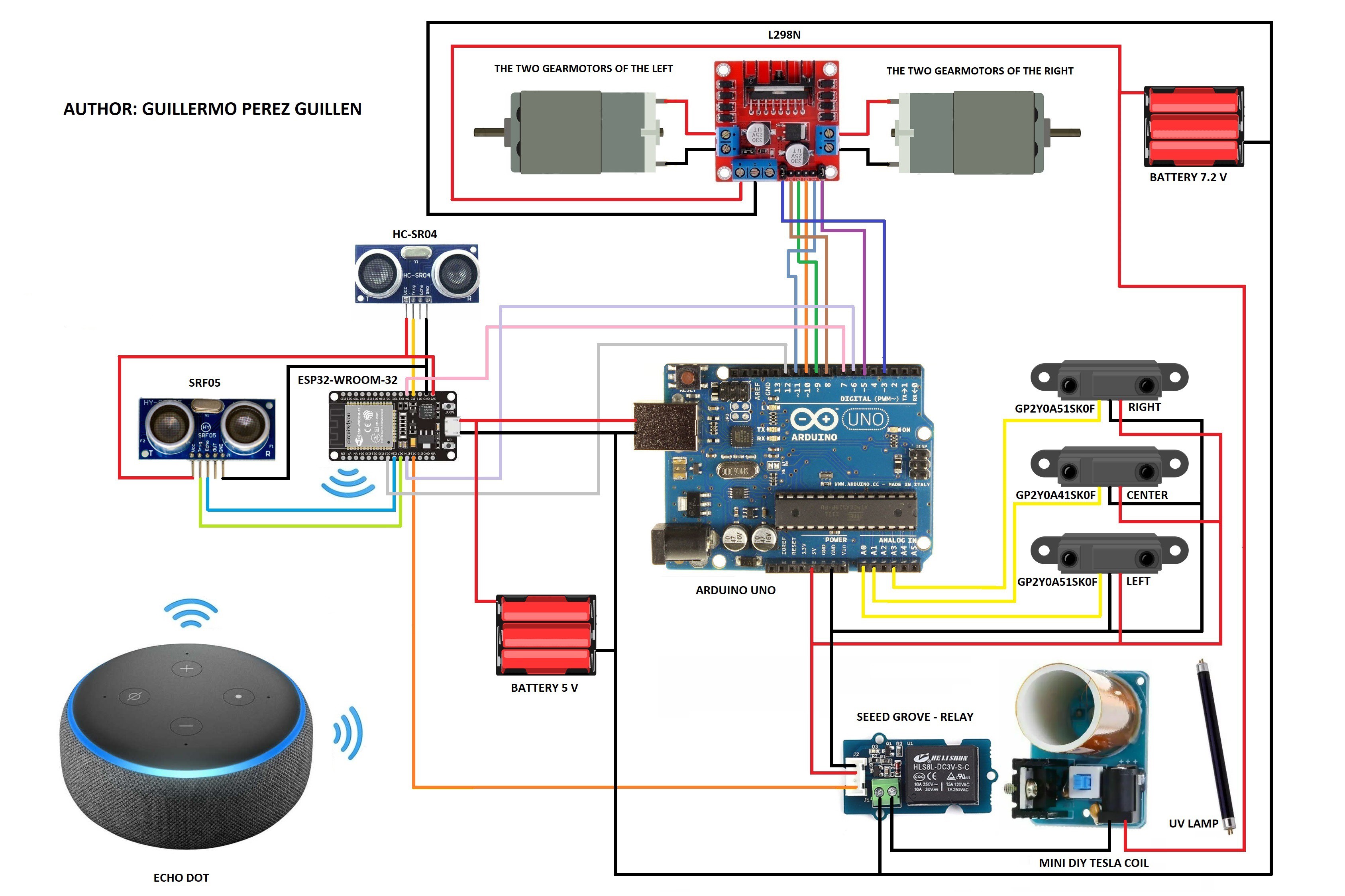
According to our schematic diagram, we make the connections of our ESP32-WROOM-32 device.
Code: esp32-wroom-32.ino
// AUTHOR: GUILLERMO PEREZ GUILLEN

#include <Arduino.h>
#include <NewPing.h> // SRFO4
#define ultrasonic_pin_1 4 // SRF04
#define ultrasonic_pin_2 25 // SRF05

const int UltrasonicPin = 2; // SRFO4
const int MaxDistance = 200; // SRFO4

const unsigned int TRIG_PIN=27; //SRF05
const unsigned int ECHO_PIN=26; //SRF05


NewPing sonar(UltrasonicPin, UltrasonicPin, MaxDistance); // SRFO4

#ifdef ESP32
  #include <WiFi.h>
  #define RF_RECEIVER 13
  #define RELAY_PIN_1 12
  #define RELAY_PIN_2 14
#else
  #include <ESP8266WiFi.h>
  #define RF_RECEIVER 5
  #define RELAY_PIN_1 4
  #define RELAY_PIN_2 14
#endif

#include <RCSwitch.h>

#define SERIAL_BAUDRATE 115200

#define WIFI_SSID "XXXXXXXXXX"
#define WIFI_PASS "XXXXXXXXXX"

#define LAMP_1 "lamp"
#define LAMP_2 "car"

fauxmoESP fauxmo;

RCSwitch mySwitch = RCSwitch();

// Wi-Fi Connection
void wifiSetup() {

  // Connect
  Serial.printf("[WIFI] Connecting to %s ", WIFI_SSID);
  WiFi.begin(WIFI_SSID, WIFI_PASS);

  // Wait
  while (WiFi.status() != WL_CONNECTED) {
    Serial.print(".");
    delay(100);
  }
  Serial.println();

  // Connected!
  Serial.printf("[WIFI] STATION Mode, SSID: %s, IP address: %s\n", WiFi.SSID().c_str(), WiFi.localIP().toString().c_str());
}

void setup() {
  pinMode(ultrasonic_pin_1, OUTPUT); // SRF04
  digitalWrite(ultrasonic_pin_1, LOW); // SRF04

  pinMode(ultrasonic_pin_2, OUTPUT); // SRF05
  digitalWrite(ultrasonic_pin_2, LOW); // SRF05
  pinMode(TRIG_PIN, OUTPUT); // SRF05
  pinMode(ECHO_PIN, INPUT); // SRF05

  // Init serial port and clean garbage
  Serial.begin(SERIAL_BAUDRATE);
  Serial.println();

  // Wi-Fi connection
  wifiSetup();

  // LED
  pinMode(RELAY_PIN_1, OUTPUT);
  digitalWrite(RELAY_PIN_1, LOW);

  pinMode(RELAY_PIN_2, OUTPUT);
  digitalWrite(RELAY_PIN_2, LOW);

  mySwitch.enableReceive(RF_RECEIVER);  // Receiver on interrupt 0 => that is pin #2

  // By default, fauxmoESP creates it's own webserver on the defined port
  // The TCP port must be 80 for gen3 devices (default is 1901)
  // This has to be done before the call to enable()
  fauxmo.createServer(true); // not needed, this is the default value
  fauxmo.setPort(80); // This is required for gen3 devices

  // You have to call enable(true) once you have a WiFi connection
  // You can enable or disable the library at any moment
  // Disabling it will prevent the devices from being discovered and switched
  fauxmo.enable(true);
  // You can use different ways to invoke alexa to modify the devices state:
  // "Alexa, turn lamp two on"

  // Add virtual devices
  fauxmo.addDevice(LAMP_1);
  fauxmo.addDevice(LAMP_2);

  fauxmo.onSetState([](unsigned char device_id, const char * device_name, bool state, unsigned char value) {
    // Callback when a command from Alexa is received.
    // You can use device_id or device_name to choose the element to perform an action onto (relay, LED,...)
    // State is a boolean (ON/OFF) and value a number from 0 to 255 (if you say "set kitchen light to 50%" you will receive a 128 here).
    // Just remember not to delay too much here, this is a callback, exit as soon as possible.
    // If you have to do something more involved here set a flag and process it in your main loop.

    Serial.printf("[MAIN] Device #%d (%s) state: %s value: %d\n", device_id, device_name, state ? "ON" : "OFF", value);
    if ( (strcmp(device_name, LAMP_1) == 0) ) {
      // this just sets a variable that the main loop() does something about
      Serial.println("RELAY 1 switched by Alexa");
      //digitalWrite(RELAY_PIN_1, !digitalRead(RELAY_PIN_1));
      if (state) {
        digitalWrite(RELAY_PIN_1, HIGH);
      } else {
        digitalWrite(RELAY_PIN_1, LOW);
      }
    }
    if ( (strcmp(device_name, LAMP_2) == 0) ) {
      // this just sets a variable that the main loop() does something about
      Serial.println("RELAY 2 switched by Alexa");
      if (state) {
        digitalWrite(RELAY_PIN_2, HIGH);
      } else {
        digitalWrite(RELAY_PIN_2, LOW);
      }
    }
  });

}

void loop() {
  delay(25);
  int rf_sensor_left = sonar.ping_cm(); // SRFO4

  if (rf_sensor_left<30){digitalWrite(ultrasonic_pin_1, HIGH);} // SRFO4
  else {digitalWrite(ultrasonic_pin_1, LOW);} // SRFO4

  digitalWrite(TRIG_PIN, LOW); // SRFO5
  delayMicroseconds(2); // SRFO5
  digitalWrite(TRIG_PIN, HIGH); // SRFO5
  delayMicroseconds(10); // SRFO5
  digitalWrite(TRIG_PIN, LOW); // SRFO5

  const unsigned long duration= pulseIn(ECHO_PIN, HIGH); // SRFO5
  int rf_sensor_right = duration/29/2; // SRFO5

  if (rf_sensor_right<30){digitalWrite(ultrasonic_pin_2, HIGH);} // SRFO5
  else {digitalWrite(ultrasonic_pin_2, LOW);} // SRFO5

  Serial.print("Distance1: ");
  Serial.println(rf_sensor_left);
  Serial.print("Distance2: ");
  Serial.println(rf_sensor_right);
  Serial.println("  ");

  // fauxmoESP uses an async TCP server but a sync UDP server
  // Therefore, we have to manually poll for UDP packets
  fauxmo.handle();

  static unsigned long last = millis();
  if (millis() - last > 50000) {
    last = millis();
    Serial.printf("[MAIN] Free heap: %d bytes\n", ESP.getFreeHeap());
  }

  if (mySwitch.available()) {
    if (mySwitch.getReceivedValue()==6819768) {
      digitalWrite(RELAY_PIN_1, !digitalRead(RELAY_PIN_1));
    }
    if (mySwitch.getReceivedValue()==9463928) {
      digitalWrite(RELAY_PIN_2, !digitalRead(RELAY_PIN_2));
    }
    delay(600);
    mySwitch.resetAvailable();
  }
}
You need to modify the following lines to include your network credentials.
#define WIFI_SSID "XXXXXXXXXX"
#define WIFI_PASS "XXXXXXXXXX"
What are the functions of ultrasonic sensors?
- These sensors measure distances that will be useful for calculating the neural networks on the Arduino UNO board. These sensors can't be directly connected to the Arduino UNO board, because they have time delays in calculating distances and therefore, the neural network calculations would not be in real time.
- With the SRF05 ultrasonic sensor we have created the necessary code that doesn't need any library. However, you need to install the NewPing library in order to control the HC-SR04 Ultrasonic Sensor. The NewPing library provides additional functions, such as the option of making a median filter to eliminate noise, or using the same pin as trigger and echo, which allows us to save many pins in case of having multiple ultrasound sensors. Here you can download the NewPing library.
Alexa, Discover Devices
With the circuit ready, and the code uploaded to your ESP32-WROOM-32, you need to ask alexa to discover devices. Say: “Alexa, discover devices”. It should answer as shown in the figure below.
 Alternatively, you can also discover devices using the Amazon Alexa app, and you can download the App here: Amazon Alexa
Discussions
Become a Hackaday.io Member
Create an account to leave a comment. Already have an account? Log In.