Ted Yapo
-
Frame Order
11/20/2016 at 13:45 • 0 commentsJust a random thought - maybe I should switch the RGB flash order to have the least-ghosting colors first. Since the ghost-correction algorithm is never going to be perfect, you'll always be able to detect at least some subtle ghosting. In looking at the tests I've done so far, ghosts of the future seem much more disturbing than ghosts of the past. Either your used to perceiving after-images from moving objects, or the notion of them doesn't seem odd. Pre-images of what is about to happen is outside our normal experience, and looks really distracting in the GIF loops. If I put the flashes in R (least ghosting), B (medium ghosting), and G (most ghosting), the ghosts are mostly from past frames, which should look less distracting. I think.
-
More Frames?
11/18/2016 at 15:05 • 7 comments1 million farmes/second is cool (I still have a way to go before I get there), but 3 total frames is limiting. How can we take more frames?
More LEDs?
The first thought is more LEDs, but without more color sensors, there's a problem. To reconstruct the individual frames, we use the inverse of the matrix M:
but, if M isn't square, there isn't an inverse. With more LEDs than color sensors in the camera, we end up with an indeterminate system and no unique solution. To get more frames with more LEDs we need more than just the red, green, and blue sensors in the camera.
CYGM Sensors
Before the modern DSLR era, camera manufacturers flirted with 4-color sensors in some point-and-shoot consumer cameras. About a dozen different models were produced in the late 1990s and early 2000s. The Wikipedia article discusses these cameras and their cyan, yellow, green, and magenta sensitive pixels. If I could find one of these cameras on Ebay, I might be able to coax four frames out of it if I could find appropriate LEDs. It seems like a lot of work for one more frame (now 33% more frames!), but it's a possibility.
Multiple Cameras
Synchronizing a mechanical shutter with events on the microsecond scale is not likely to be possible. It would be possible to capture the same three instants from multiple viewpoints using multiple cameras. That could be interesting - multiple cameras at different viewpoints is how the original bullet-time special effects in The Matrix were done, but it doesn't give more frames.
It might be possible to simulate having more color sensors by using narrow-band color filters on a number of cameras. Since the response of the red, green, and blue pixels on the camera sensor are pretty wide, several narrow-band filters could be used (with different cameras) to capture light from several different colored LEDs. Maybe at most, you might do {royal blue, blue, cyan, green, yellow, red, deep red} for seven frames, maybe requiring seven cameras. Again, this sounds like a lot of work (and expense) for a mediocre gain.
-
Moving Dice Test
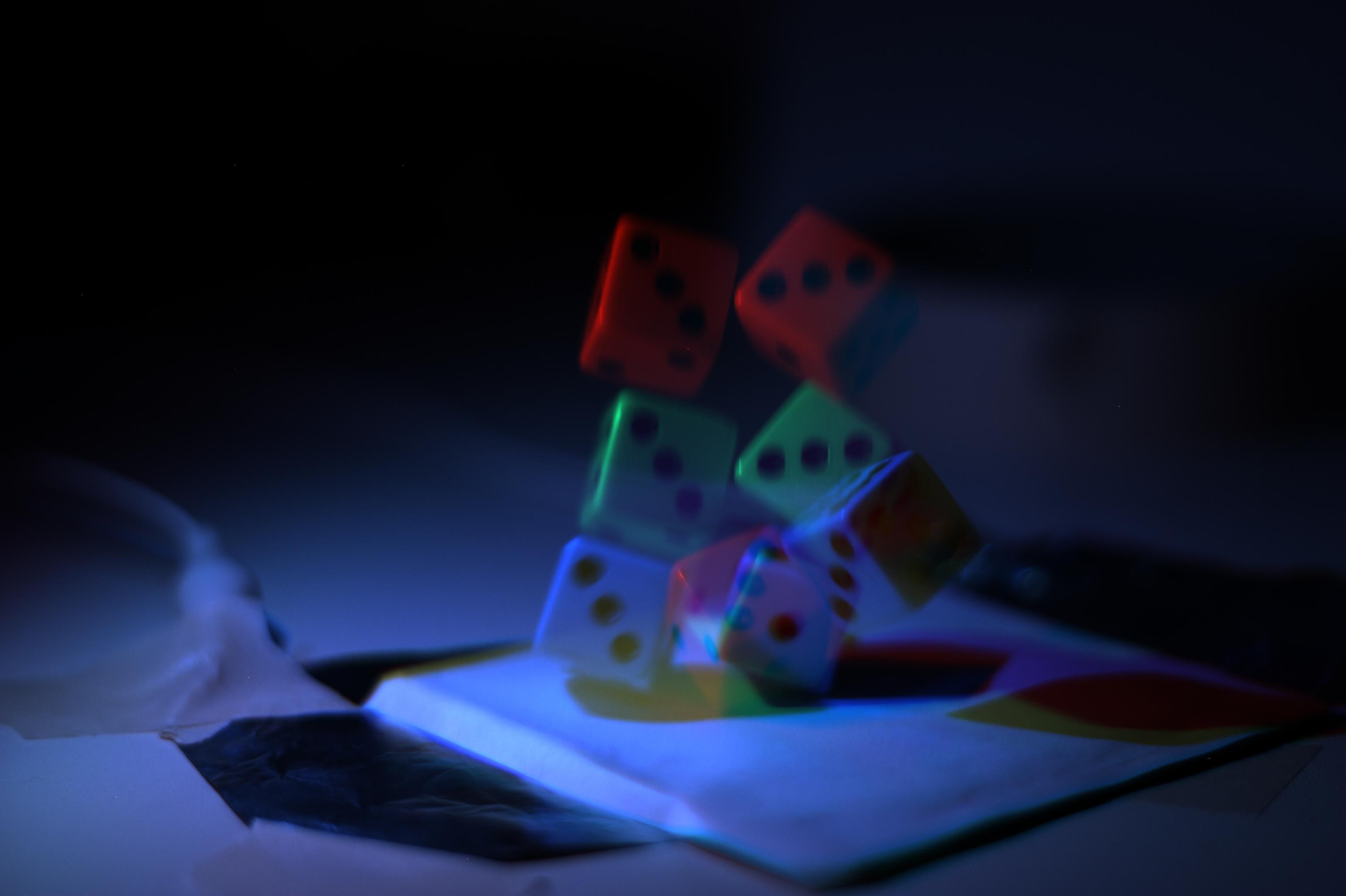
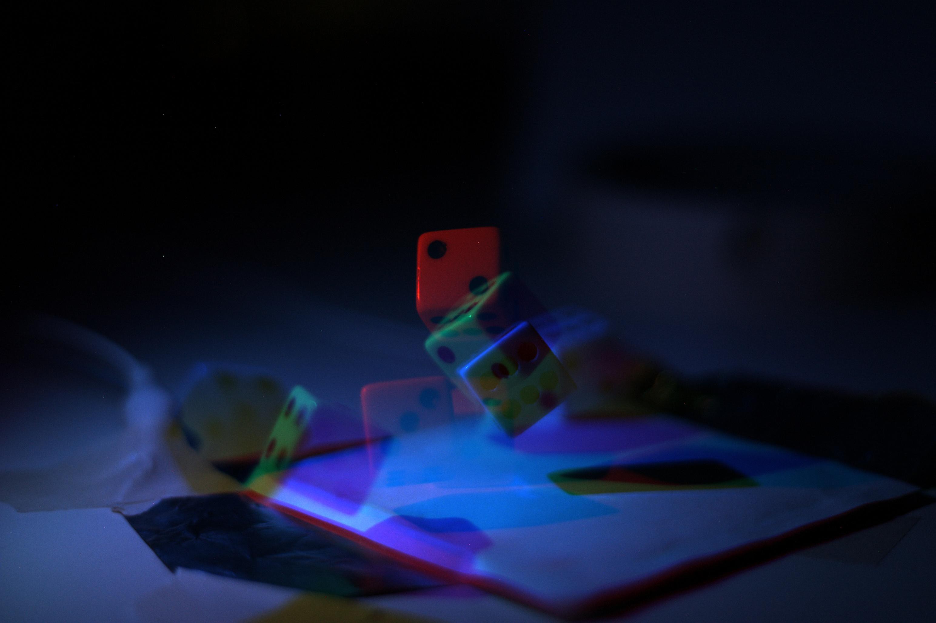
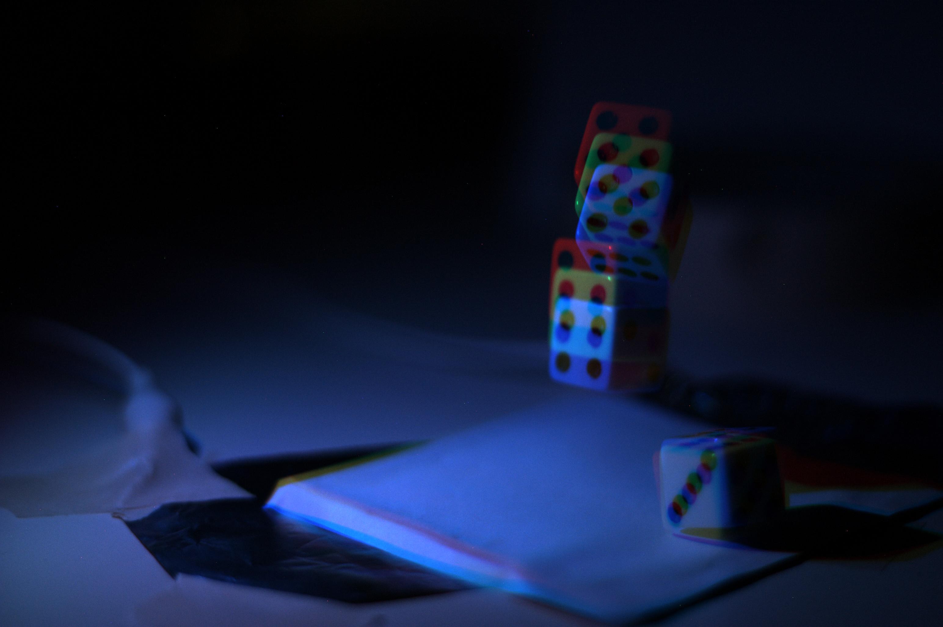
11/18/2016 at 04:10 • 6 commentsIt turns out that you can make some 3-frame animations of rolling dice with just the 3W red, green, and blue LEDs driven with normal BJTs and 1k resistors from an Arduino. I used two pieces of aluminum foil as a trigger - the falling die presses one against the other, closing the circuit. It's a pain-in-the-ass to adjust, but I got it to work OK for some tests.
![]()
The flash sequence starts when the die hits the table, so this sequence is of the subsequent bounce. I experimented with 1 ms flashes, then moved to 200 us. From these experiments, I think if I can get 100x more light than I'm getting from these single-chip LEDs (driven below their rated current), I should be able to take some initial bullet photographs. More would be better :-)
What's Wrong?
There are a few issues I have been able to identify so-far:
- Some pixels (especially in the blue channel) are saturated 255. The ghosting-correction algorithm fails for these pixels. I think the only solution is to ensure no pixels in the image are saturated in any channel. The saturated areas in the above image are easy to spot.
- The brightnesses of the three channels don't match. I applied some hard-coded corrections to these animations, but I think I need to write an automatic brightness adjuster to eliminate this annoying effect
- The ghost-correction calibration has to be done at the same LED current used for the actual flash. I just used my original test calibration for this sequence, and it doesn't work that well. The problem is that the LED colors shift somewhat (blue shift) at different currents. To get the best images, a calibration will need to be done with the same duration and current flashes used for the photograph.
There are obviously issues to fix, but it seems like this is going to work. If I can get 1 us flashes bright enough, that's the equivalent of 1 million non-overlapping frames per second (for a 3-frame burst).
Gallery
Here are some other test images, shown along with the original RGB frame from the camera:
![]()
![]()
![]()
![]()
![]()
![]()
![]()
![]()
![]()
![]()
-
What can I do with just the 3W LEDs?
11/18/2016 at 02:22 • 0 commentsSo, I started thinking ... I used 1 second exposures (G, B, anyway) for the original still dice images. To get the correct exposure, I had to set the camera to ISO 100 and the lens to f/22. The ISO will go up to 3200, and the lens opens to f/1.8 (I cannot justify buying the very nice Canon f/1.4 or the coveted f/1.2). At these settings, the camera is:
times as sensitive. I should be able to use 210 us flashes and get the same exposure! That should be fast enough to capture the dice in motion, even using lousy 1-chip 3W LEDs driven with a BJT and a resistor.
I have to get down to the bench now.
I think I can make a simple trigger with two pieces of aluminum foil that get pressed together by falling dice.
-
References
11/17/2016 at 20:30 • 0 commentsAs usual, I started this project by diving in and building something. Now, it might be time to do some research on the topic ;-) I found some interesting references, so I'll list them here (and update as I find more). I've just started, so this list is probably totally incomplete.
When I still had access to an academic library, I found a paper from the 1960s (I believe) that discussed red, green, and blue flashes from filtered gas discharge lamps to capture three instants in time on a single color film emulsion. This was in maybe 2009. I haven't been able to find it again since (and no longer have access to the library).
LED Manufacturers
Cree weighs in with this whitepaper:
How much current can you use? Their opinion "it depends." They also state "For duty cycles less than 10%, do not exceed more than 300% of the maximum rated current". Unfortunately, this just isn't going to produce enough light. Although LED efficiency drops dramatically at higher currents (due to an effect known as "droop"), you still typically get more light with more current.
Commercial LED Strobes
There was a Kickstarter for the "Vela One," and LED strobe that boasts 500ns pulses with white LEDs:
https://www.kickstarter.com/projects/vela/vela-one-the-worlds-first-high-speed-led-flash
They claim they drive 9 LEDs (they don't say how many chips per "LED", although I'd guess they are 50 or 100W LEDs) at 20x their normal brightness. If this is true, it means more than 20x their normal current. Comments in the Hackaday article listed below would indicate they observed a 50% reduction in efficiency, meaning 40x the normal current.
This device:
http://smartvisionlights.com/downloads/datasheets/XR256_Datasheet.pdf
claims 288 mm^2 of LED chip area at 180A, but is designed as a rapid strobe light instead of emitting a single-flash. This works out to 625 mA/mm^2. I have already run 30A into two paralleled 30x30mil chips. If my math is correct, that's about 26A/mm^2. A huge difference. Of course, they do this up to 5,000 time per second for long periods. I would count myself very lucky to get 5,000 total flashes from my device before it fails.
Gardasoft, who make industrial LED illuminators, have a nice whitepaper about overdriving LEDs:
http://www.gardasoft.com/Downloads/
See their "APP930 - Overdriving LEDs" document; I can't link directly to it here. They claim that overdriving current by 100x is OK for 1us pulses. The 45x45 mil "3W" chips I intend to use are rated for 500 mA (documentation varies). 100x overdrive would be 50A/chip.
Hackaday Articles
This one was written up on Hackaday.
https://hackaday.com/2015/10/05/frozen-time-photography-with-a-100w-led/
This one used a 60V supply and a 100W white LED. An interesting project, but as expected, the really useful information is in the comments. I just found this one, so I haven't digested them all, but a brief glance didn't reveal any showstopper issues. I knew brightness was a problem.
Academic Papers
Here's an article with a similar LED pulser (again monochromatic: white or green):
http://citeseerx.ist.psu.edu/viewdoc/download?doi=10.1.1.474.6388&rep=rep1&type=pdf
I haven't read this one thoroughly, yet either. Most interesting line in skimming the paper: "For pulse widths below 5μs the maximum pulse current is limited to If ≈ 250 A". That's a lot of current, and it makes me happy.
This one uses three filtered xenon flashes for schlieren photography. I have only read the abstract:
http://spie.org/Publications/Proceedings/Paper/10.1117/12.209576
Here's a paper from 1995 using a CCD camcorder and filtered xenon flashes to increase the video frame rate. They claim more than 10,000 fps. They also mention "correction equations" to correct ghosting (I would imagine anyone playing with this idea would derive almost the same equations). Again, I'm not paying $18 to read this paper, so I've only looked at the abstract.
http://spie.org/Publications/Proceedings/Paper/10.1117/12.209611
-
Capacitor Tests
11/17/2016 at 15:00 • 5 commentsEven though the test board can only go to 30V (due to the FDD6630A MOSFET), I decided to try the three different capacitors to see how they performed.
MLCC
This was the baseline test I discussed before. I used (5) 10uF 25V MLCCs in a 1206 package, soldered in parallel on the board (upper middle/right):
![]()
I had the probe leads soldered on backwards, so the current pulse looks negative. The capacitors are rated at 25V, so I only tested at 24 max. At this voltage, the peak current as measured across the 125 milliohm resistor is 21.9 amps. You can also see how the pulse slopes due to the capacitor voltage drooping as it discharges.
![]()
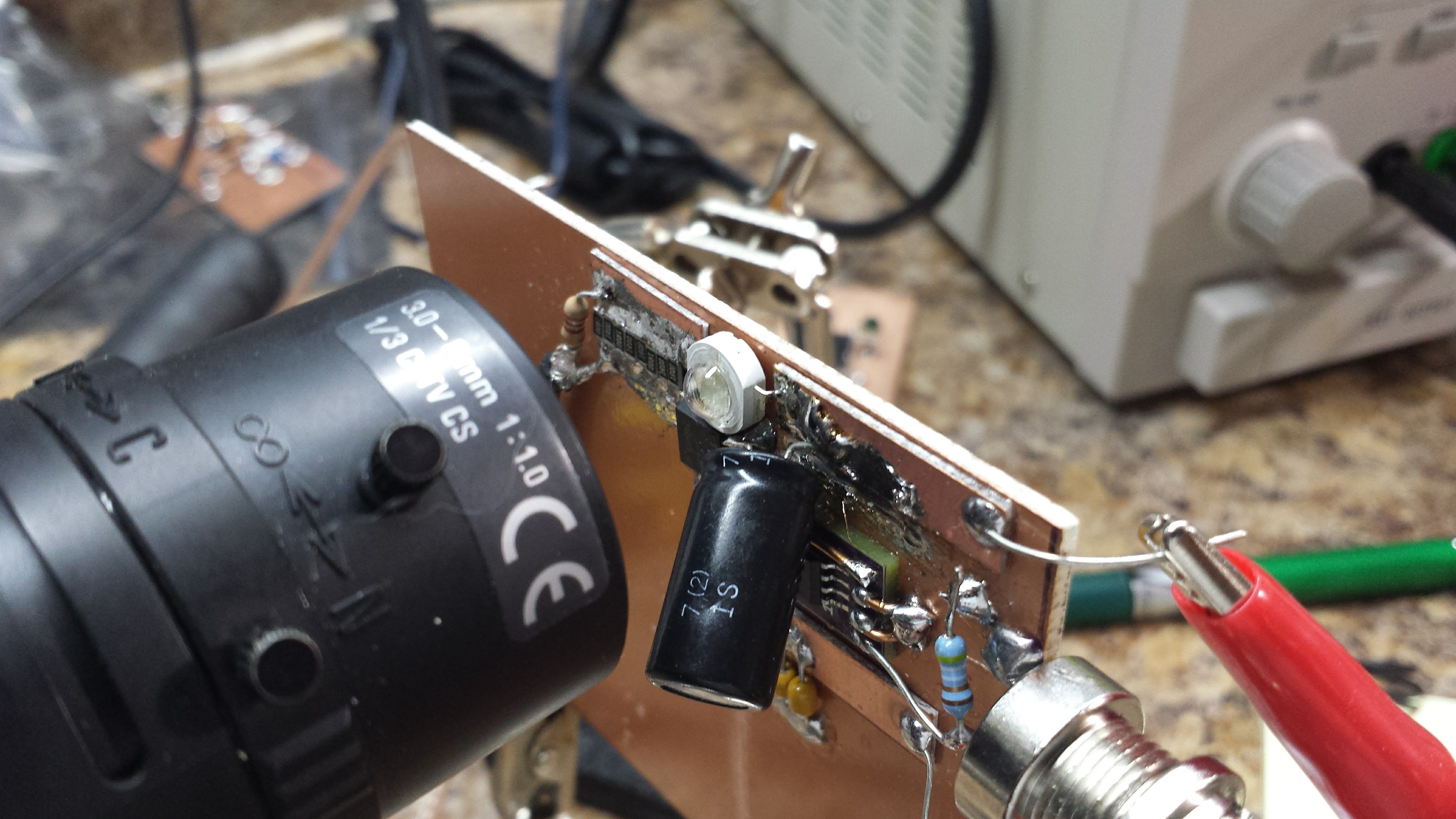
Photoflash Capacitor
This test was with a 40 uF 320V "photoflash" capacitor I bought on Ebay. I don't have any specs for this cap, other than the nominal capacitance and working voltage. I'm pretty jaded about this kind of purchase at this point, but I figured I'd give it a shot. The capacitor measured 53 uF on one of my DMMs. Here it is, soldered on the board. While the iron was hot, I also corrected the probe leads to make the pulse look positive on the scope.
![]()
Here's the current waveform with a 24V supply. The peak current is 15.2 amps - less than the MLCC because of the higher ESR of the electrolytic cap. You can also see a little bit of an overshoot/ring at the leading edge, which I think may be due to ESL in the capacitor, although the rise time isn't substantially slower. Maybe there's just enough ESL to inductively "peak" the rise time? One nice thing about this capacitor is that it has enough storage so that the voltage doesn't droop during the pulse. This is despite the fact that nominally, this part has less capacitance (40 uF) than the 5 paralleled 10uF MLCCs. At the applied voltage, the MLCC capacitance drops while this one stays relatively constant. Another plus is that this capacitor is by far the cheapest of the three I tested - I got 100 of them on Ebay for $14!
![]()
You can compensate for the additional series resistance in this capacitor by turning up the voltage. Here's what the pulse looks like at a 30V supply:
![]()
The current is now around 20.2 amps. I'm limited to 30V because of the MOSFET on this board - and that's ignoring any derating on Vdss. Since this capacitor is rated for 320V (if the heat-shrink sleeve is to be believed), there should be no problem getting much more current from it.
Overall, I was pleasantly surprised by this capacitor, especially considering the price. I thought the ESR and especially the ESL would be much worse.
Metalized Polyester Capacitor
This film cap is huge on the board. I could have made the leads a little shorter, but not much:
![]()
I think the size of this capacitor and the lead length result in some series inductance that slow the pulse down. I forgot to take a screenshot at 24V, but did get one at 30V:
![]()
The leading edge is a bit slower and more rounded than I would have expected, and you can see the voltage droop during the pulse. This capacitor is only 10uF, so that's not surprising - although it still has less droop than the "50 uF" of MLCCs. Where this capacitor really shines is in ESR. The peak current (at 30V supply) is 29.4 amps, as opposed to 20.2 for the photoflash cap. This is the cap you want if the system voltage is constrained by other factors. Even so, with the voltage rating of 250V, you could get a ridiculous amount of current from these caps - but, as discussed before their dv/dt rating would limit them to 150 A.
Conclusions
There isn't a perfect capacitor for a circuit like this; each one has it's pros and cons. I've summarized my qualitative thoughts on these three:
Capacitor ESR ESL Cap. loss w/ Voltage Size Cost MLCC excellent excellent bad tiny high Film excellent OK excellent HUGE
high Photoflash good good/excellent excellent medium
low I think I'm going to try going with the photoflash cap for now. @K.C. Lee suggested "generic" high-voltage electrolytics instead of photoflash caps (the idea being that the available documentation is much better and that they're used successfully in other pulse applications). I'll look around my parts bins for some to try. About the only thing I'd like to see improved over the photoflash cap I've tested would be a smaller ESR. I can compensate with a higher voltage, but this means a higher voltage MOSFET and regulator, too. You can get 50% more current at the same voltage with the film cap, but at at 10x the cost and in a much bigger size.
I also like the added capacitance from the electrolytic and the resulting flat-topped pulse with little droop. It's a double-edged sword, though. If the trigger circuit fails (it's software!), and creates a very long pulse, all the capacitor energy gets dumped into the LED. With smaller capacitors, I'd have less concern for the LED. Larger capacitors could store enough energy to permanently damage the LED chips. I'll just have to be careful.
I can also see that I'll need to add bleeder resistors and similar safety features into the flash circuits, since the voltages will probably get above the "safe to handle" range.
-
#FAILLOG : First Flash Driver Prototype
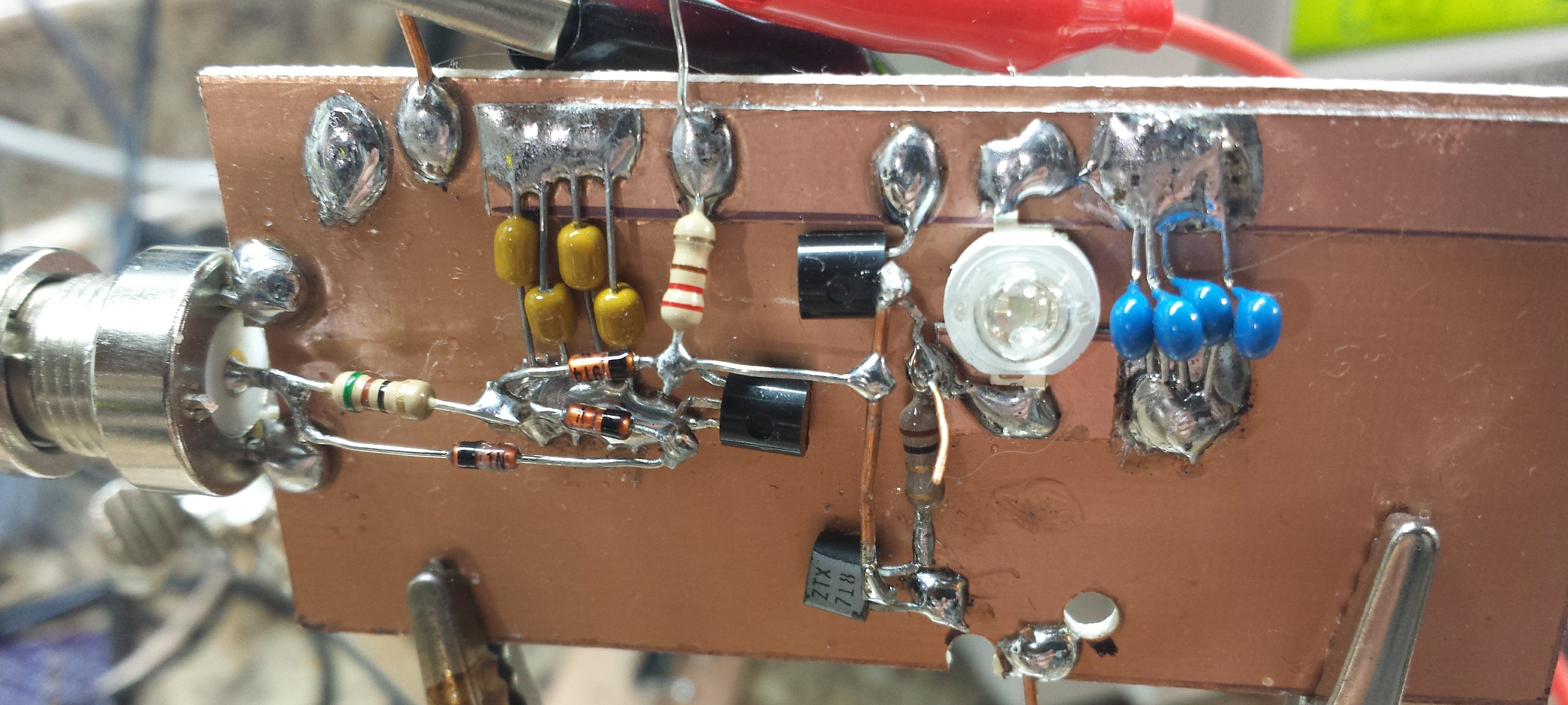
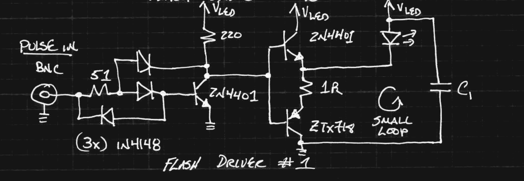
11/16/2016 at 16:33 • 9 commentsI made this one before I had any of the MOSFET gate driver ICs. Of course, you could argue that the BJTs I've used here could make nice gate drivers themselves (the ZTX718 lists that as a primary application on the datasheet). But, I decided to see what I could do with BJTs alone.
![]()
I made this from jellybeans, because everyone has jars of them lying around. The ZTX718 doesn't qualify, but I originally had a 2N4403 in there instead :-)
![]()
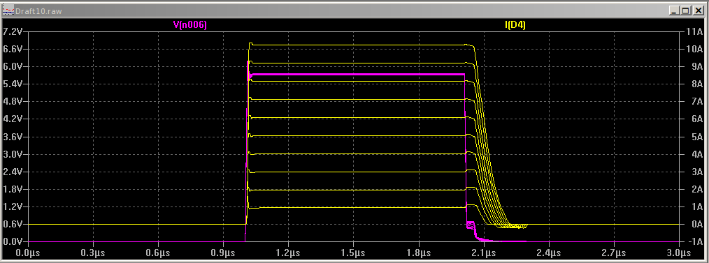
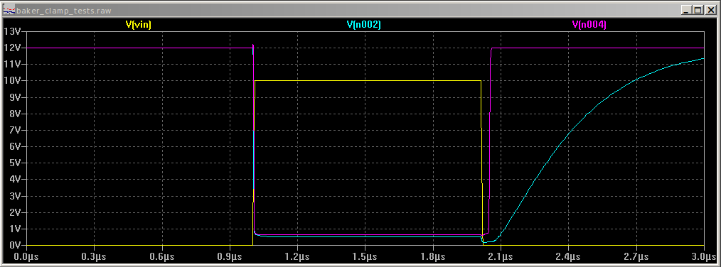
I worked hard to overcome the storage time in the first common-emitter stage, hauling out the big guns: a three-diode Baker clamp. In simulation it appears to work pretty well. Here are the current pulses through the LED (yellow) for supply voltages from 6 to 24V compared with the input pulse (magenta):
![]()
On the bench, though, as I turned up the voltage, the storage/fall time got longer and longer - much worse than this simulation. I accidentally deleted the oscilloscope screenshots, so I'll have to update this log later. I have two suspicions. First, the supply voltage may have been sagging due to the heavy current pulses, so there wasn't enough drive through the 220-ohm resistor during the falling edge. Another possibility is bad layout (I know you're eyeing those big current loops). I'm still interested in figuring this out, but I've basically abandoned this circuit for the flash. I had originally thought it would be useful to have a number of these circuits driving individual LEDs in a big array. I might end up back there, but for now, I think a smaller number of drivers each with a handful of LED chips is the way to go, and MOSFETs with commercial driver ICs eliminate the storage time issues entirely.
Baker Clamps
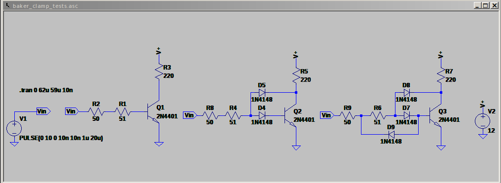
I did take the opportunity to explore various baker clamp topologies in simulation, though. Here are some interesting results. Three circuits I compared:
![]()
From left to right, no clamp, a 2-diode clamp, and a 3-diode clamp. They're all driven from a 50-ohm source resistance. Here are the waveforms:
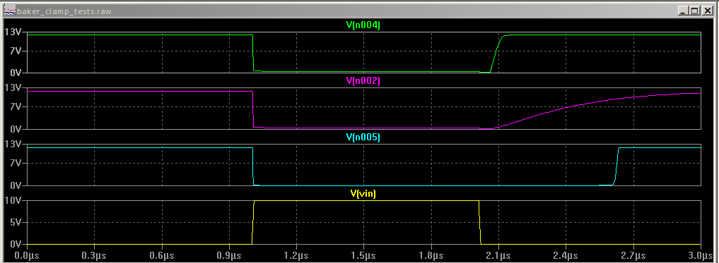
![]()
On the bottom is the driving waveform (before the source resistance). The top trace shows the output of the three-diode clamp, which doesn't show appreciable storage time. In the middle is the 2-diode clamp. I didn't expect the exponential tail here. Finally, with no clamp, you see about 500 ns of delay between end of the input and output pulses.
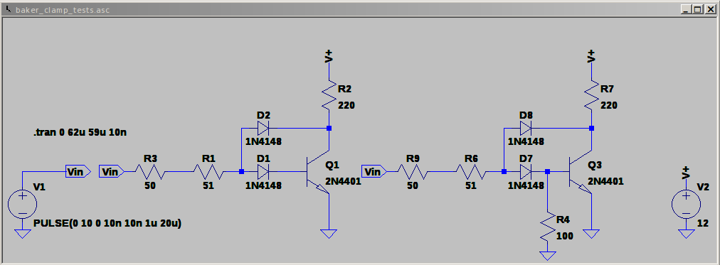
The tail on the 2-diode clamp bothered me - the problem is that the input can't pull the base down through the diode. This gets fixed in the 3-diode version with another (reverse) diode, but you can also add a resistor to pull down the base (right hand side):
![]()
This resistor does a good job of eliminating the tail (magenta trace has R4, cyan trace does not):
![]()
I find it very interesting that this base resistor is omitted from most discussions of the 2-diode Baker clamp. Maybe because the original circuit was made with germanium PNPs (and possibly Ge diodes) in the 1950s, and they didn't require this resistor?
Schottky Clamps
Of course, you can do even better with a Schottky clamp:
![]()
The Schottky cuts off another 50ns or so (cyan trace) of the 3-diode version (magenta):
![]()
I knew this when I built the circuit above, but I used the 1N4148s because I couldn't find any of my through-hole Schottky's when I went to assemble it, and I didn't feel like dealing with SOT-23's (I easily found the reel of BAT54s).
-
Second Flash Driver Prototype
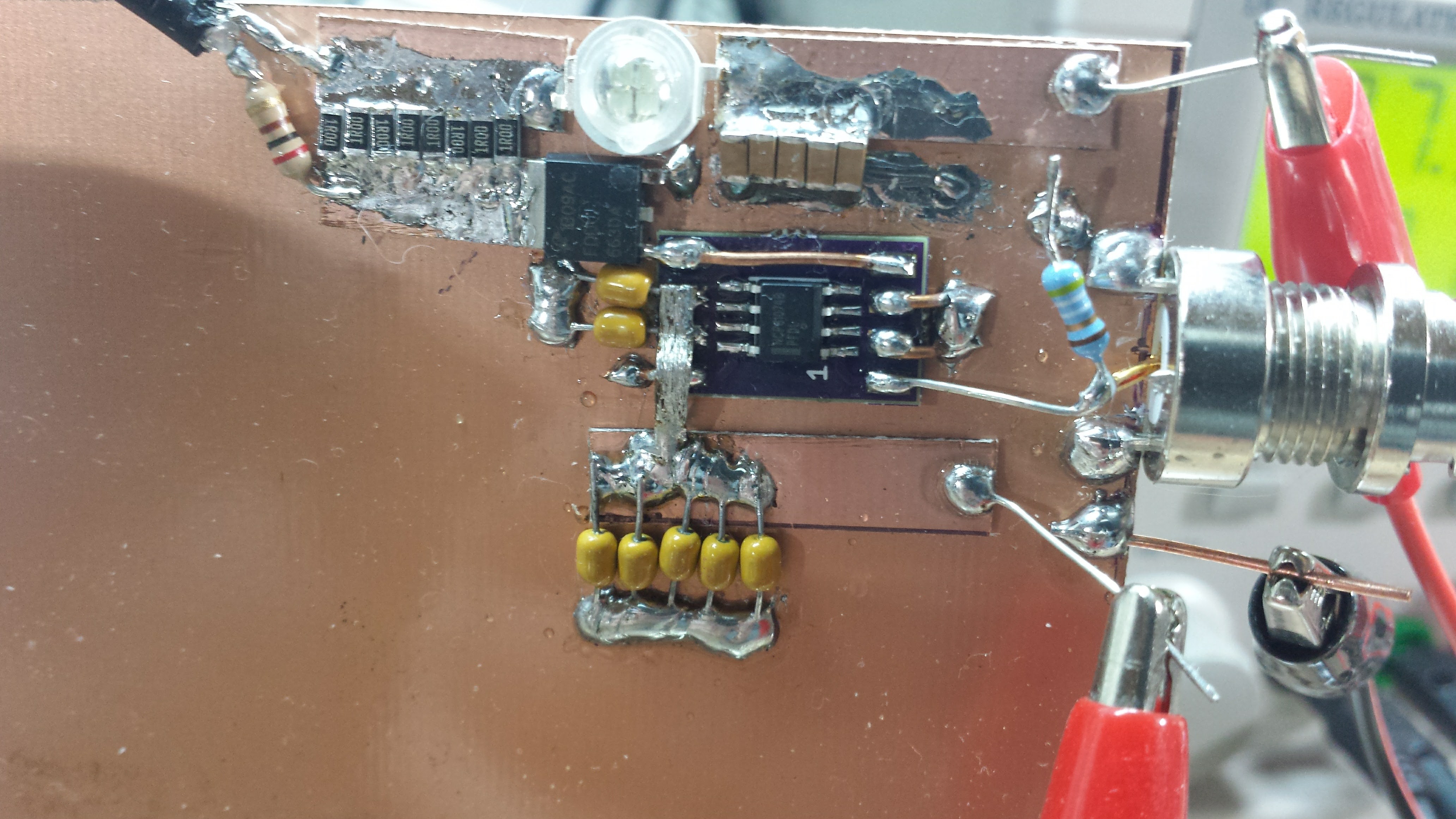
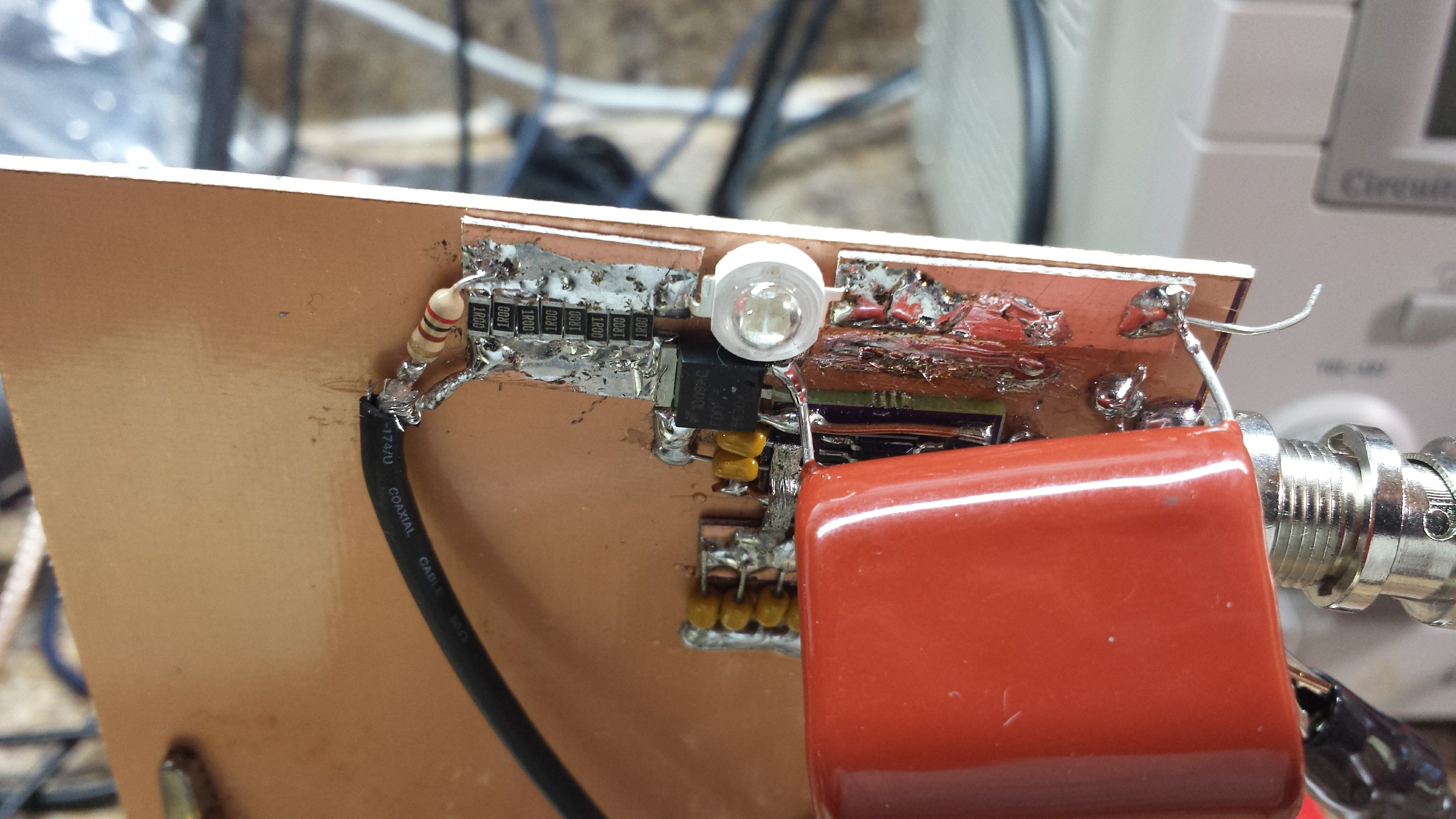
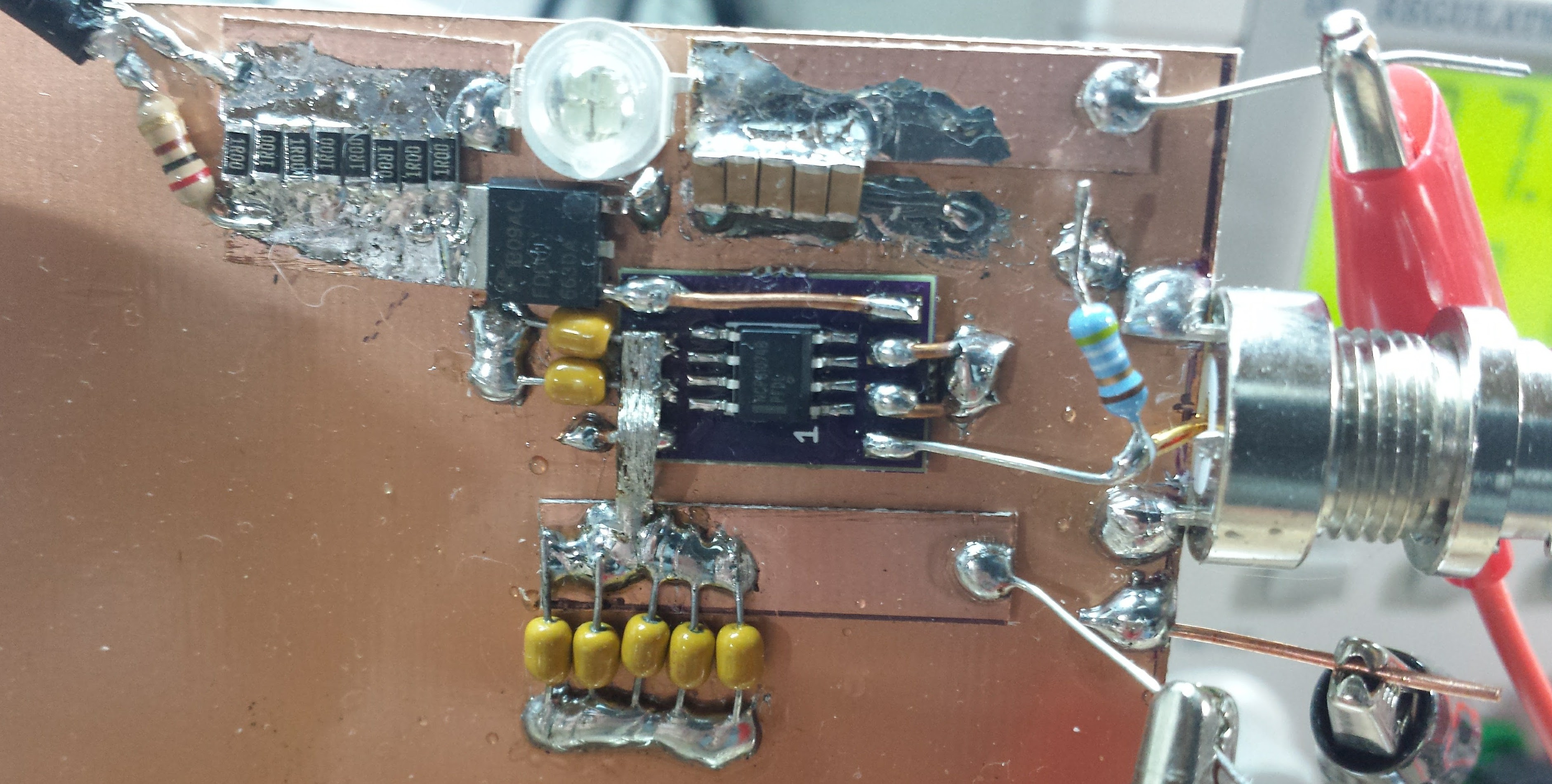
11/15/2016 at 22:01 • 9 commentsWhere's the first one, you ask? I'll write it up in a bit: a log of how reality sometimes clashes with your understanding of the world (it didn't work too well). In any case, the second one demonstrates the principles, although it will need scaling up to provide enough light for good images. Here's the assembly:
![]()
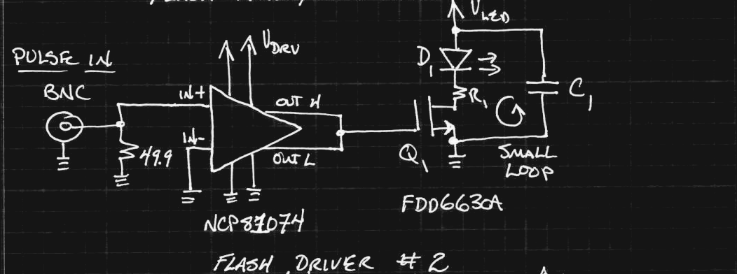
and the schematic:
![]()
I built this one when I only had the MLCC capacitors available, so I used five of them in parallel (upper right on the board) for C1. The yellow caps are bypass for the MOSFET driver voltage. I also didn't have any low-valued resistors for R1, so I paralleled 8 1-ohm ones for a resulting 125 milliohm. This helps ballast the LEDs against temperature effects, and provides a convenient place to sense the current. The NCP81074 MOSFET driver serves double duty here as a line receiver and gate driver, while the FDD6630A MOSFET switches the current. You can see the layout allows the current to flow in a small loop through C1, D1, R1, Q1, and back to C1. The LED is a Chanzon "5W" green led that has four 30x30 mil chips connected in series/parallel.
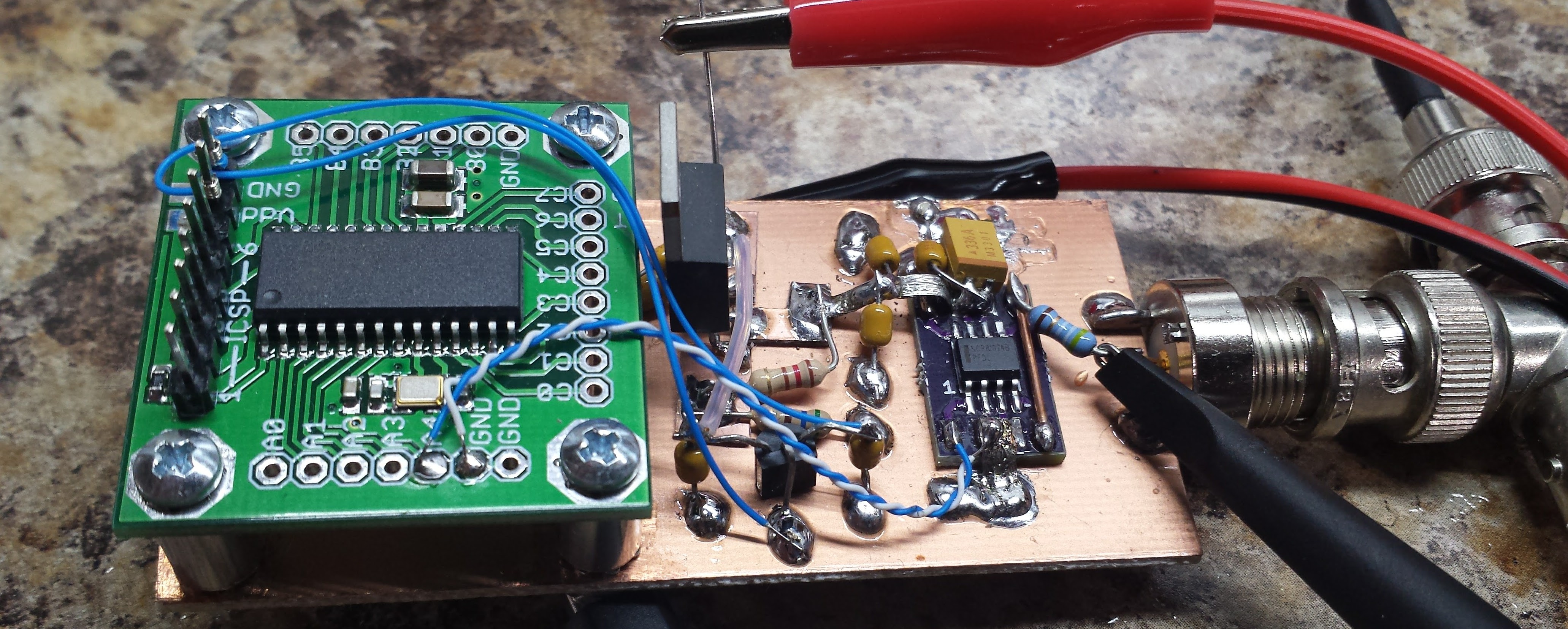
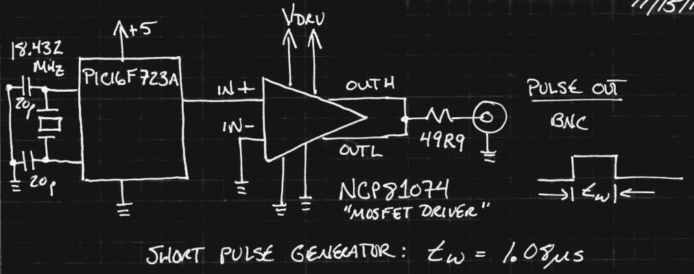
Prototype Controller
I drove the input with a quick prototype of the controller - a PIC16F723A generating 1.08 us pulses every second or so. I had a few breakout-type boards made for this processor at one point since I had used them in a few projects:
![]()
The cable driver is another NCP81074, as shown here:
![]() Measurements
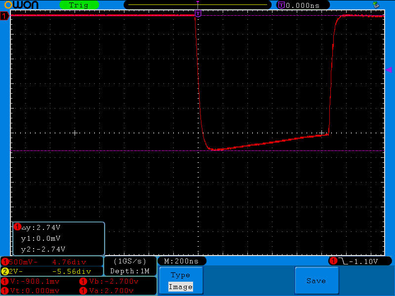
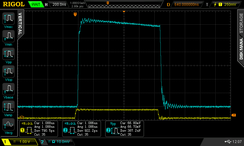
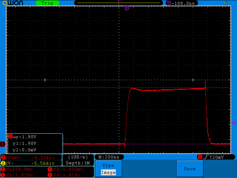
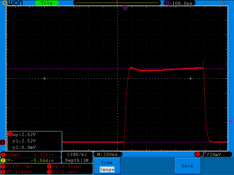
MeasurementsI used a battery-powered "floating" oscilloscope to probe the current through R1 in the flash circuit. I keep an otherwise "just OK" Owon SDS7102 around because it runs off batteries and can be connected between any two points in a circuit like this. I simultaneously measured the light output of the LED chips with the biased photodiode probe discussed in the previous logs. Here are the traces using a 24V supply for the LED voltage:
![]()
![]()
The 2.74V peak across the 125 milliohm R1 equates to about 22A of current through the LED chips, or about 11A for each paralleled string of two. The current pulse looks "negative" because of the way I soldered the probe onto the board :-) The detected light pulse (cyan) is shown along with the driving pulse from the PIC (yellow) on the other scope. The original electrical and detected optical pulse widths are essentially identical (measured 1.088 vs 1.086 us) despite the cyan somehow appearing longer.
I thought there were two interesting things in these measurements. First, the "50 uF" of capacitance looks like a smaller value according to how much the current droops during the pulse. That was expected for MLCC's, anyway. The shape of the detected light pulse is also roughly the same as that of the current pulse. This means that the LED is still operating in a monotonic mode (more current -> more light). I read a whitepaper that said at some point, the LED can stop outputting more light with added current. In the high current regime, we're way above the most efficient operating point of the LEDs anyway, but it makes absolutely no sense to use more current for no added illumination.
Next Steps
This circuit could go higher (the MOSFET is rated at 30V), except the capacitors are rated at 25V. The next step is to build another prototype with more suitable parts and more LED chips and see how it works.
I know this small prototype doesn't deliver anywhere near the light I need, but it would be interesting to see exactly how many of these 1 us pulses I need for a decent exposure with the camera. That would give me a solid feel for how much I need to scale things up.
-
System-level Design
11/15/2016 at 17:57 • 0 commentsBlock Diagram
Here's the big-picture design for the system. I'm envisioning a trigger/timer/controller board and separate LED flash driver boards to ease staging the photographs. The controller will look something like this:
![]()
I'm not sure which PIC I'll end up using: for this application, it doesn't seem to matter that much. I have a 18.432 MHz xtal drawn in because that's what I had available for prototyping. This allows a 217ns code timing resolution, which is plenty fine enough, and also keeps the UART baud rates exactly on spec - maybe I'll stick with this frequency. Using 5 instruction cycles for an LED pulse results in 1.08 us.
The timing function is triggered by one or both photogates (amplifier and comparator design TBD). These can sense a milk drop or rifle projectile in flight. Using both gates with a known spacing allows the projectile velocity to be determined. I have also thought about a sound-based trigger, which I will probably experiment with a little.
The UART lines run (through a USB-UART bridge) to a PC where timing parameters can be downloaded to the system.
I'm not sure what connectors to use for the LED voltage ports yet. Maybe banana jacks, since they're all DC.
VLED Regulators
Since the R, G, and B LEDs have different forward voltages and different brightnesses, a variable voltage source will be provided for each color (the 'ADJ REG" blocks above). These can be tuned to balance the flash brightnesses, and accommodate different flash driver circuits.
![]()
A cheap 10-bit DAC drives a cheap linear regulator through a level-shifting op-amp. I've used this type of circuit before, and it works well for a digitally-controlled voltage source. The LM317 only works up to 36V, so if I need more than that, I'll have to look for a different regulator. I'd like to stick with integrated solutions, here, though. The combination of thermal and over-current limiting built into these things is hard to beat.
The PIC controls the 3 DACs through SPI.
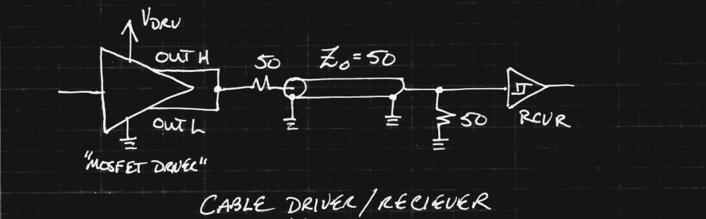
Cable Drivers
I am a sucker for double-terminating cables. Although you could get good waveforms with a simple back-termination here, I'm adding the receiver terminations, too, for noise immunity. With maybe a hundred amps switching in neighboring LED channels, I don't want accidental triggers - the 50 ohm termination may help somewhat.
![]()
Since I'm going to be using integrated MOSFET gate drivers for the flash circuits, I figured I'd use them as cable drivers, too. They seem perfect for the job - fast edges, a controllable voltage level, and plenty of current drive. The problem with double-termination is that it cuts your signal in half, but with these drivers, you can just set Vdrv to twice the desired swing to compensate.
I initially made some prototypes with NCP81074 drivers from ON Semiconductor. These work great, but I can only find the "B" variety in stock - they have an input threshold set to one half the driver voltage. The "A" variety have fixed-level logic thresholds, but are nowhere to be found. I'd ideally like to have both available - the logic threshold version for the cable driver (which gets driven from the PIC), and the 1/2 Vdd version for the receiver (for noise immunity). I ordered some Microchip MCP1406's, which are a little slower, but still fine for this application. I can use the Microchip parts for the logic-threshold cable drivers and the ON Semi parts for the receivers / MOSFET drivers (their intended use!) on the flash board(s).
-
Which Capacitor?
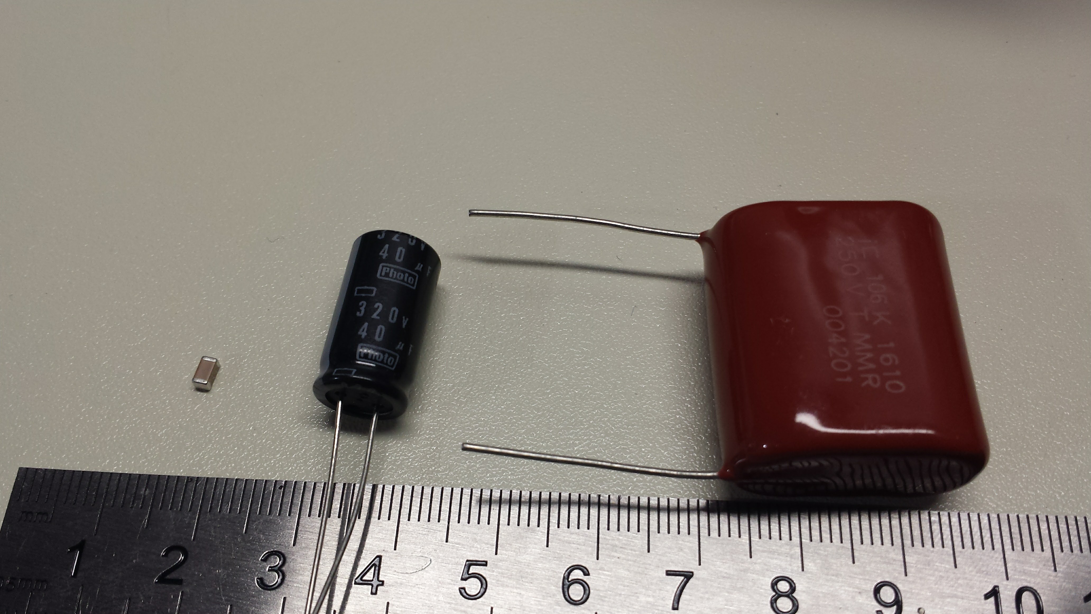
11/15/2016 at 04:58 • 10 commentsI've been playing with a couple of circuits for driving LEDs with short, high-current pulses (so far up to about 10 amps per LED chip). At microsecond pulse lengths, this isn't the kind of current you get through wires from your supply; this is the kind of current you draw from local capacitors, planning the current path in tight loops to minimize inductance. So, I need some capacitors. I found some surprising things while researching them. Here are the three types I've looked into:
![]()
On the left is a 10uF 25V MLCC (1206 package). Center, we have a 40uF 320V photoflash capacitor. You don't find too many with smaller capacitance than this. Finally, we have a 10uF 250V metalized polyester capacitor. These things each have their drawbacks.
MLCC
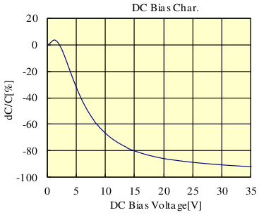
The multi-layer ceramic capacitor is a modern wonder - how do they pack 10uF of capacitance into that tiny case? They use lousy dielectrics that lose most of their capacitance with applied voltage. Here's a curve I pulled from one of the datasheets for a 10uF 35V cap:
![]()
The curve shows the change in capacitance vs the applied voltage. If you use the capacitor at the rated voltage, you lose more than 90% of the capacitance - the 10uF is now less than 1uF. Of course, you always de-rate components, but even if you de-rate this voltage by a factor of 2.3 and use the cap at 15V, you've still lost 80% of the original 10uF. This graph is for an X7R dielectric, which is specified for +/-15%, but that has to do with changes over temperature, not applied voltage.
They're not all this bad. I couldn't find this graph for the capacitors I've been using, but the loss of capacitance at higher voltage is clear from the waveforms produced (detailed in the next log). A possible (expensive) workaround is to parallel many of these capacitors so that you end up with the desired capacitance at the working voltage. Even with 5 of them paralleled on my test board, I still see problems.
The second problem with these capacitors is that the dielectric is typically piezoelectric. In sensitive circuits you can get microphonic noise introduced into your signals. In my case, I have the opposite issue - the capacitors issue a troubling "snap" noise each time the LEDs are pulsed. I can only wonder if this mechanical stress will eventually damage the capacitors. I've had MLCC's "sing" before in circuits, and while it's annoying, I had never feared for their safety. This time, I'm not so sure.
Finally, these caps seem to top out at around 50V ratings. I had hoped to keep the LED flash circuits strictly low-voltage to make them safer than xenon flashtube versions, but driving high currents into strings of LEDs looks like it will take some higher voltages.
After experimenting with theses caps for a while, I've decided to look at the other two.
Photoflash Electrolytics
The second suspect is the capacitor behind the typical xenon flashtube. These high-voltage electrolytics are designed to have low ESR (equivalent series resistance) and ESL (equivalent series inductance) so they can deliver high-current pulses in the millisecond range or so. Normal electrolytics, even higher voltage types, typically aren't rated for the high pulse currents involved. I haven't tried this particular cap in the flash circuit yet, but I worry that the ESL will be too high to generate very short pulses. I can't find any specs on ESL for these, so I'll just have to try them. Electrolytic caps also have a lousy lifetime, but they're cheaper than the film types below.
Another drawback is that these specialized capacitors aren't typically stocked by the usual, reliable distributors. I was forced to find some on ebay. Who knows what I actually got.
Metalized Polyester
The last cap is probably electrically the best. I chose some 10uf 250V caps made by Illinois Capacitor - I won't be using voltages this high, but chose this unit for the current rating. These capacitors are rated for a maximum dV/dt of 15 V/us. For a 10uF capacitor, that translates to a current of 150A. I figure I can safely use them for 100A pulses or more while maintaining a healthy de-rating. As far as ESL, the datasheet states less than 1nH per mm of body and lead length - probably around 40nH mounted on a PCB - not bad at all. Finally, the ESR can be estimated from the dissipation factor, which is rated less than 1%. This document explains dissipation factor, which is:
where Xc is the capacitive reactance at the test frequency. At the 1 kHz test frequency, a 10uF capacitor has a reactance of:
So, the ESR should be less than 1% of 15.9 ohms or 159 milliohms. A 100A pulse would drop a maximum 16 volts across the ESR - with a maximum of 250V to play with, we can just crank the voltage to compensate.
The downsides are that these capacitors are huuuuge and expensive.
EDIT 20161115
I forgot to mention that some of my thoughts about capacitor selection were influenced by Don Klipsein's notes about bullet photography with traditional flashlamps. His advice is to use the foil types for the kV-level voltages involved in that kind of ultra-short xenon flash driver. My thought was that if they can deliver microsecond pulses to flashlamps, they can do the same for LEDs. Of course, with LEDs, you can easily control the flash duration by switching off the driver, instead of relying on a small capacitor to fully discharge.
Bullet Movies
Using red, green, and blue LEDs to capture short movies of very fast objects


 Measurements