Ted Yapo
-
Biased Photodetector Sensor
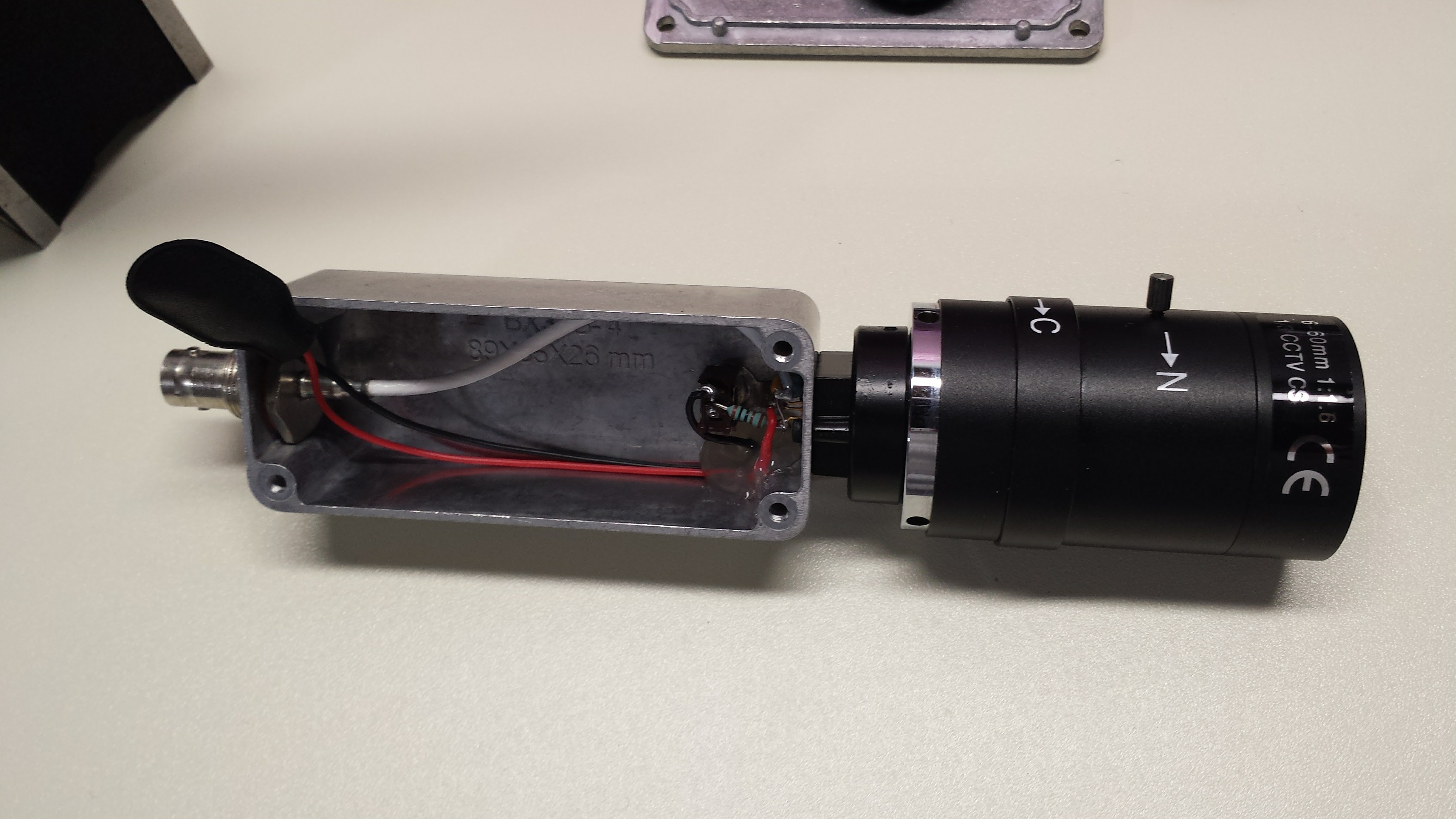
11/13/2016 at 16:13 • 7 commentsI tried two things yesterday: speeding the fall-time of the laser pulser and biasing the photodiode in the detector. Both improve performance. I ended up making this easy self-contained biased photodetector probe which shows a bandwidth of about 75 MHz. It features a C/CS - mount thread for attaching cheap surveillance camera lenses.
![]()
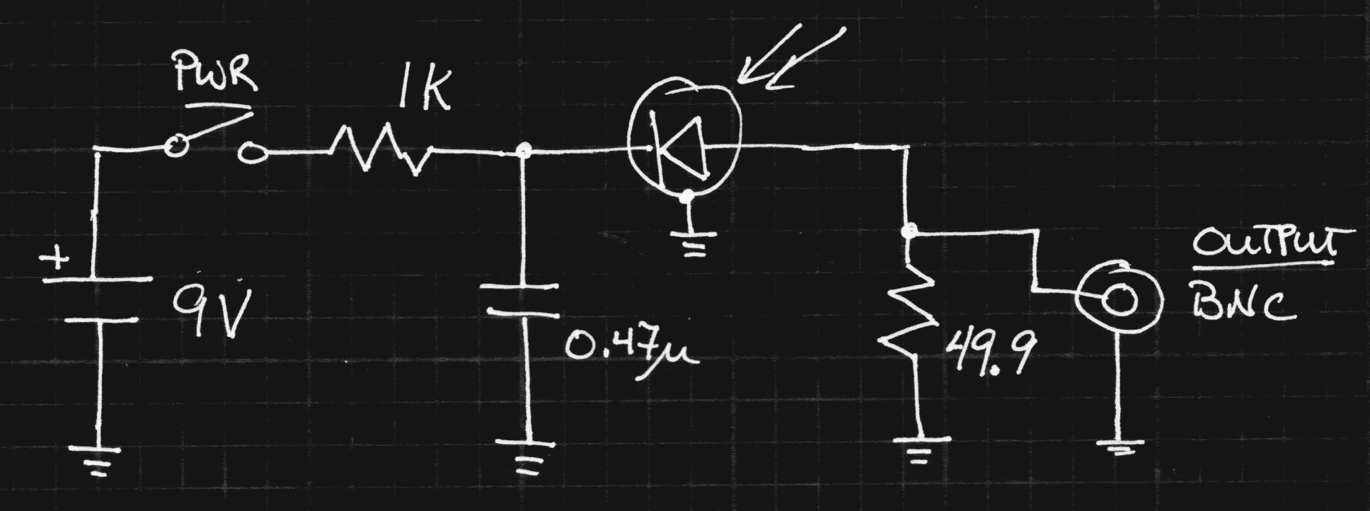
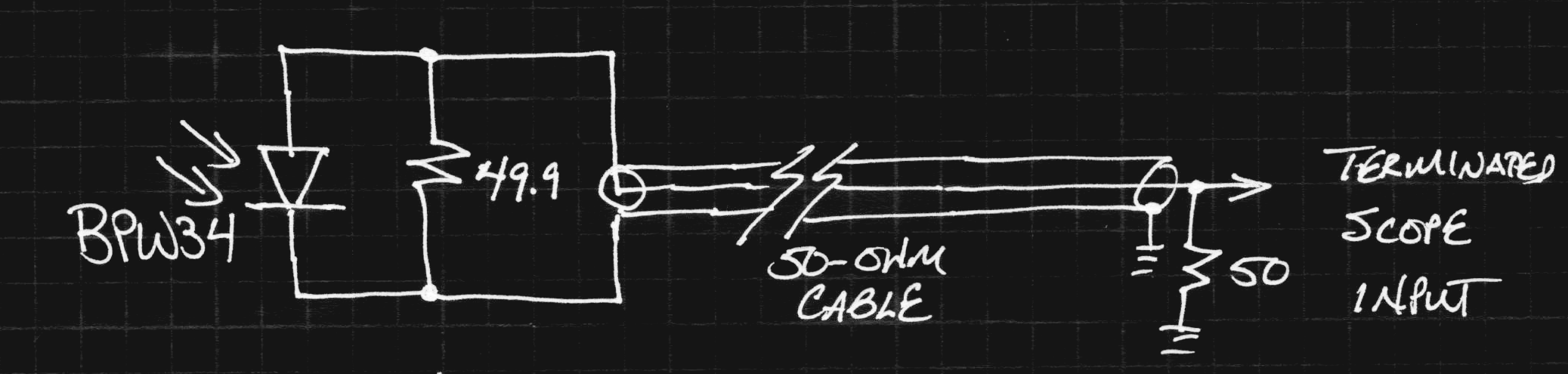
Here's the circuit, adapted from the photodiode tutorial on Thorlabs site:
![]()
I omitted a regulator, obtaining the negative bias voltage directly from the battery. I would like to have had a higher voltage, but didn't want to use a larger case with multiple batteries. I also didn't want to use a switching supply - as it turns out, this well-shielded construction provides a very clean signal. No need to mess it up with switching hash. Next time I see one, I'll pick up a lithium 9V. It will last longer and provide a nearly constant 8.4V (unlike the alkaline 9V's which end up below 6). The diode sees a 25-ohm load (50 on each end of the cable), which cuts the signal in half, but raises the bandwidth and helps avoid reflections.
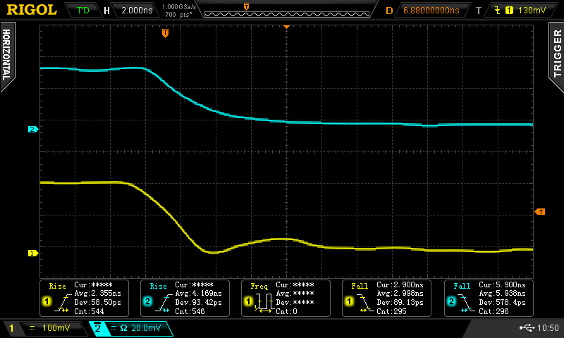
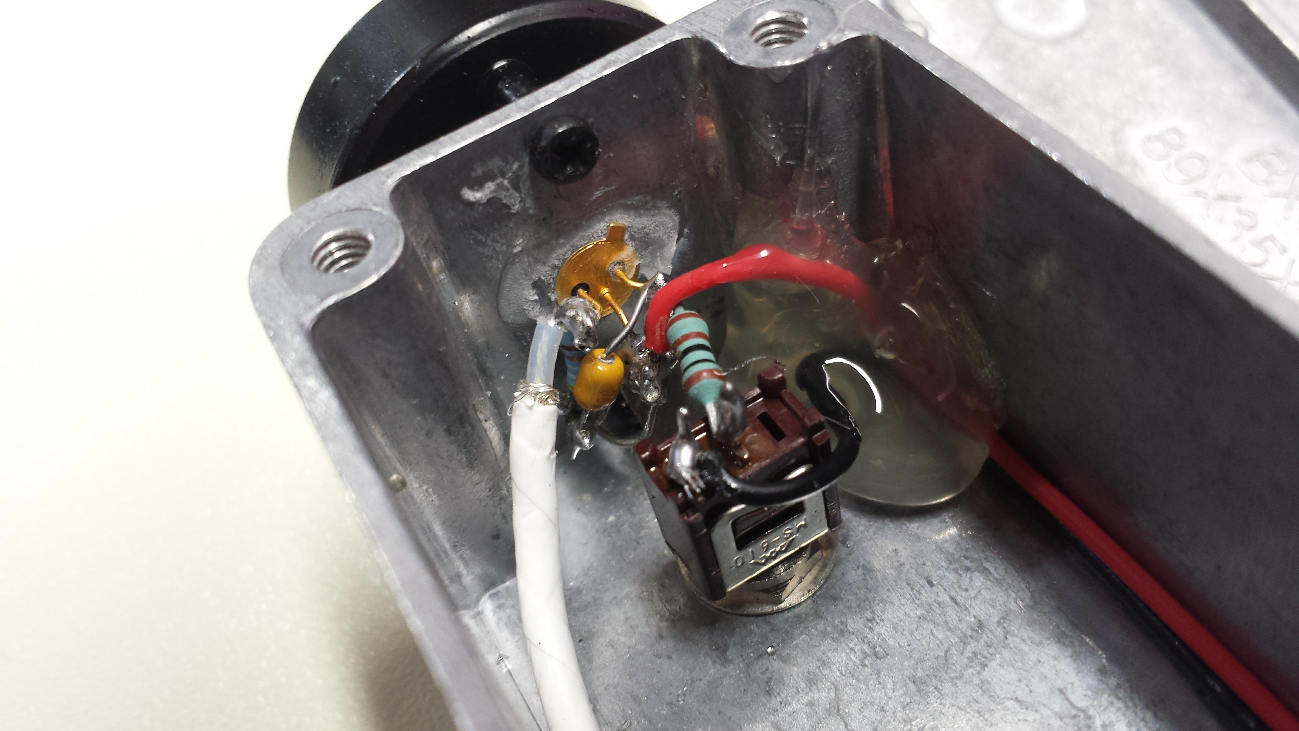
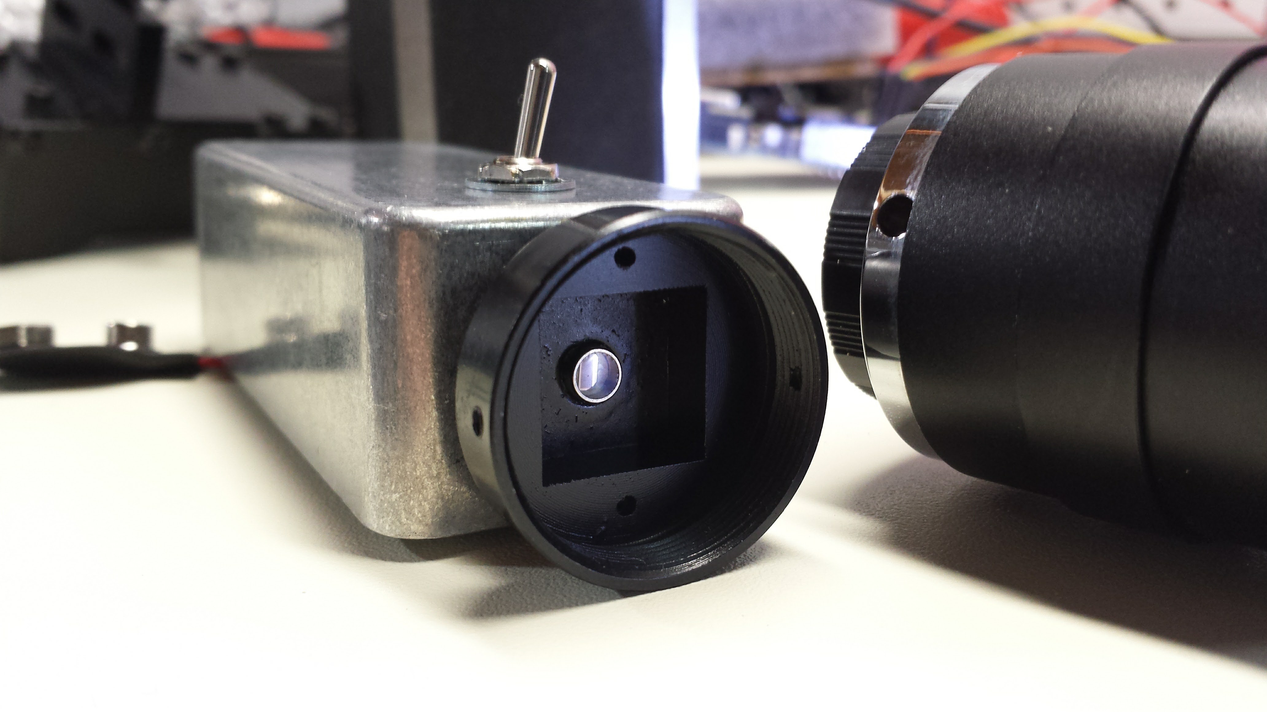
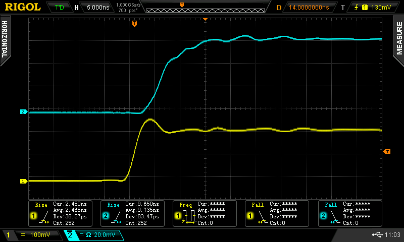
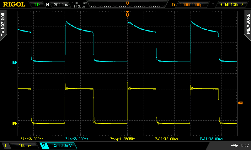
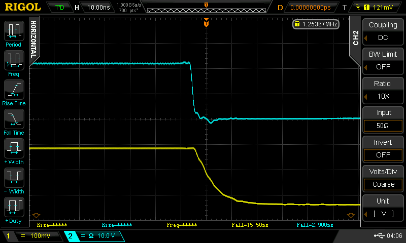
I used a surplus diode I had kicking around (Ebay, 2009). It's labeled "SD076-12-12" - probably an Advanced Photonix (now Luma) part, maybe similar to the SD076-11-31-211. That part claims rise times of 5 ns at 50V reverse bias, and with the version I have, I've seen better than that at even 9V reverse bias. I chose to use this part because it was the only (fast) one I had with an isolated cathode - it's in a three lead package (shown below) with separate connections for anode, cathode, and case. I guess cost drives manufacturers to use 2-leaded cases, but the three-lead one really helps with shielding this circuit, as shown in the schematic. Here's the rise time when the laser pulser is directed at the diode:
![]()
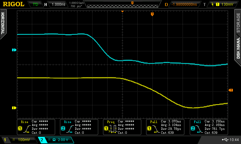
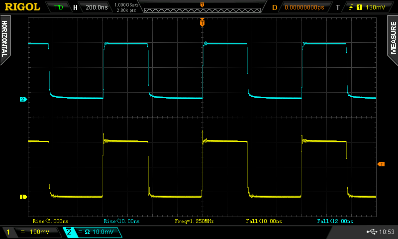
The auto-measurement on the scope pegs it at about 4.2 ns (cyan trace). There's almost no ringing: the tight construction and double-termination keep things clean. Here's the corresponding fall time:
![]()
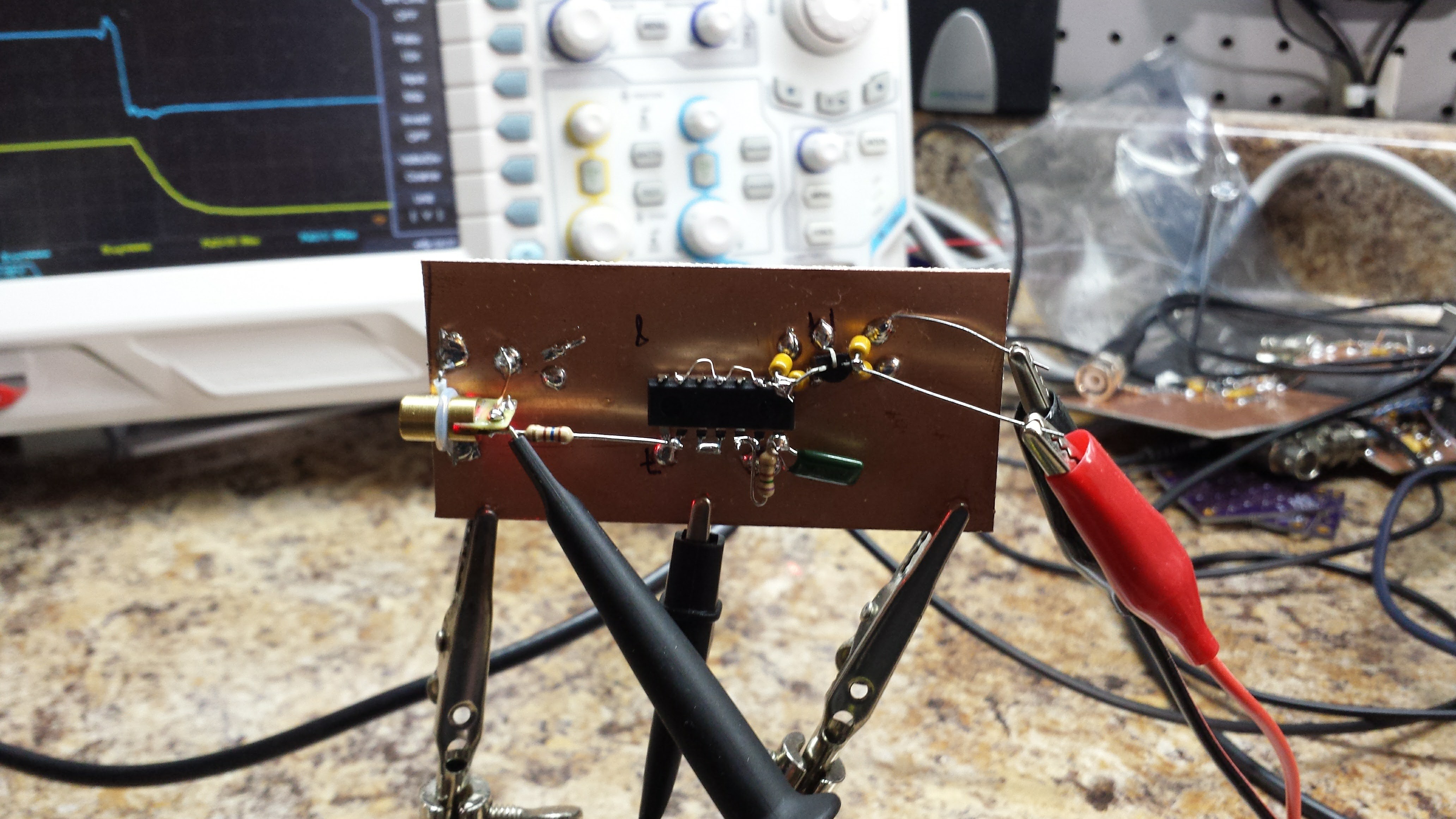
The fall time is a little longer, about 6 ns. Still not bad, and no ringing here, either. I think the nice waveforms are really helped by the construction:
![]()
Even though leaded parts are used, I tried to keep everything short and brought the 50-ohm cable right to the diode. The cs-mount is intended for board cameras, but it works just as well for attaching lenses to photodiodes. I found five of them for $7.47 on Amazon - I'm sure the same parts are on Ebay or AliExpress. They accept M2 screws.
The photodiode was inserted into a hole in the case, and held in place by soldering the case terminal to a solder lug inside. A drop of cyanoacrylate adhesive also helps keep it fixed. I painted the front of the case flat black to kill reflections. I didn't worry too much about the exact focal plane; you never want to focus light any smaller than the diode, anyway, because it causes funny non-linearities. Mostly the lens is useful for collecting more light and controlling the field of view. A CS-mount camera body cap conveniently screws on the front for protecting the diode.
![]()
What about the BPW34?
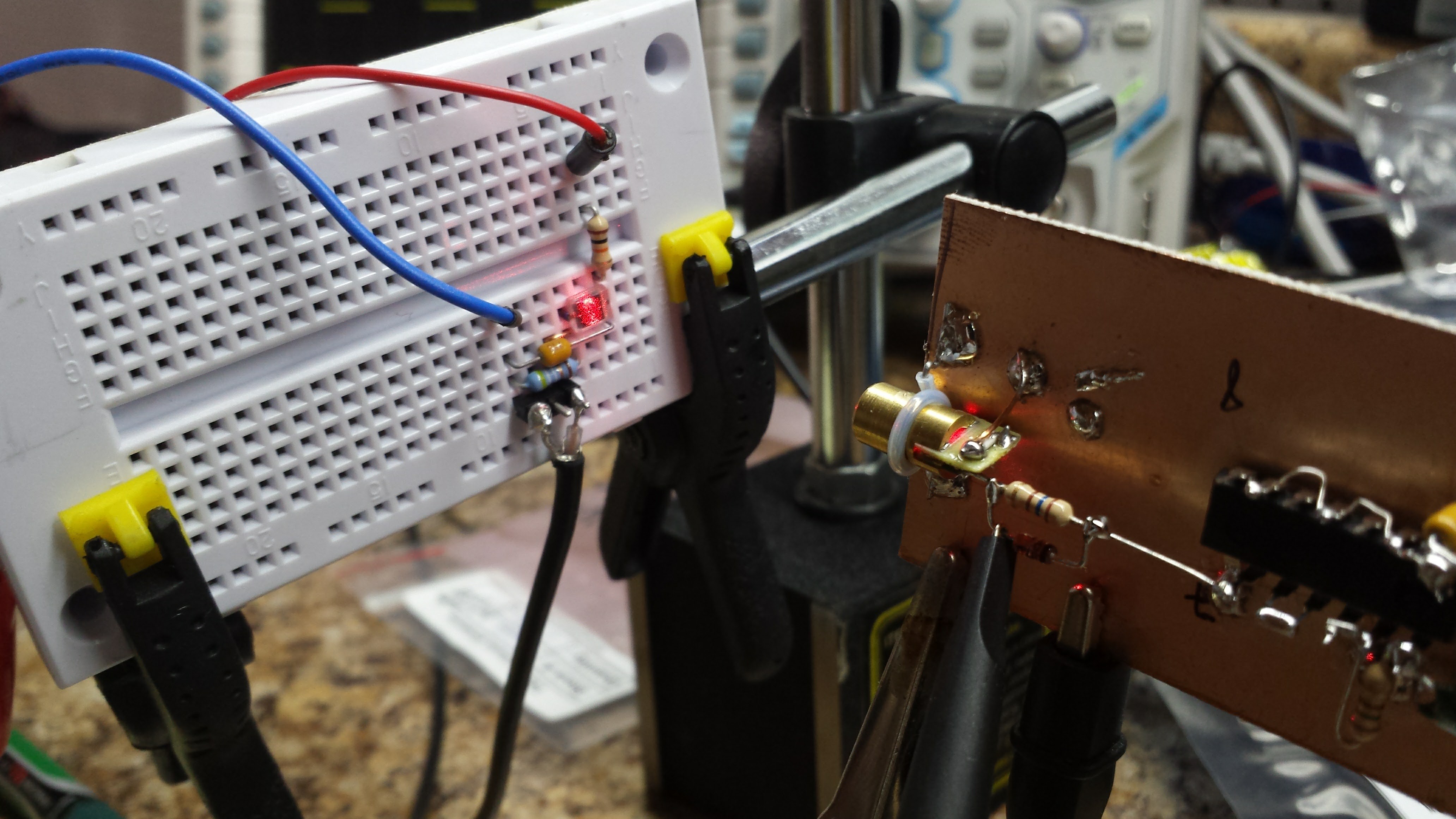
Since I can't even find documentation for the photodiode I used here, it's unlikely that anyone else will be able find one to use. So what about the lowly BPW34 that showed rise-times above 70ns unbiased? I threw together a quick breadboard to find out:
![]()
It's the same circuit shown above except using a variable supply for bias. At 5V reverse bias, you get this rise time:
![]()
All those wiggles are from the poor layout on the solderless breadboard. The scope measures about 17 ns rise time. Cranking the reverse bias to 20V speeds things up again:
![]()
Now, the rise time is under 10 ns. Using the 0.35/tr approximation, this detector has about a 36 MHz bandwidth. All these numbers are in line with Osram's datasheet, which specifies a 25 ns rise-time with 5V reverse bias into a 50-ohm load. The measured fall times are a little longer (22 ns @ -5V, 10 ns @ -20V). The only thing I don't like about the BPW34 is that it isn't shielded - shielded parts are much more expensive. I'm wondering if you could make a nice 3-terminal case out of a spent .22-caliber rifle cartridge - you don't need a front window since the BPW34 encapsulates the chip in epoxy. Or maybe just a section of brass tubing soldered to ground on a PCB.
Improving the Pulser
The slower fall time of the laser pulser was bothering me, so I tried a few things to speed it up. The first experiment was adding a small speedup capacitor across the 160-ohm resistor. This sped up the edge, but also made things ring badly - I suspect my poor layout - look at that long resistor lead in the image above. Speedup caps and stray inductances make for some ringy pulses.
The next experiment was adding a reverse diode across the resistor to help pull charge out of the laser diode junction during turn-off. I was looking for 1N5711's, but I found a bag of FDH700's first. I don't know if they make this diode anymore, but it's like a 1N4148 on steroids - 1.5 pF of junction capacitance and a 900 ps switching time (the 1N4148 is 4ns - too slow to help here). If you find your bag of 1N5711's first, they might be even better. In any case, here's the fall time with the diode in place (measured with the APD module):
![]()
The fall time is now around 2.2ns, where it had been around 2.9 before. Not perfect, but I'll take it.
Mysterious Photodiode Behavior
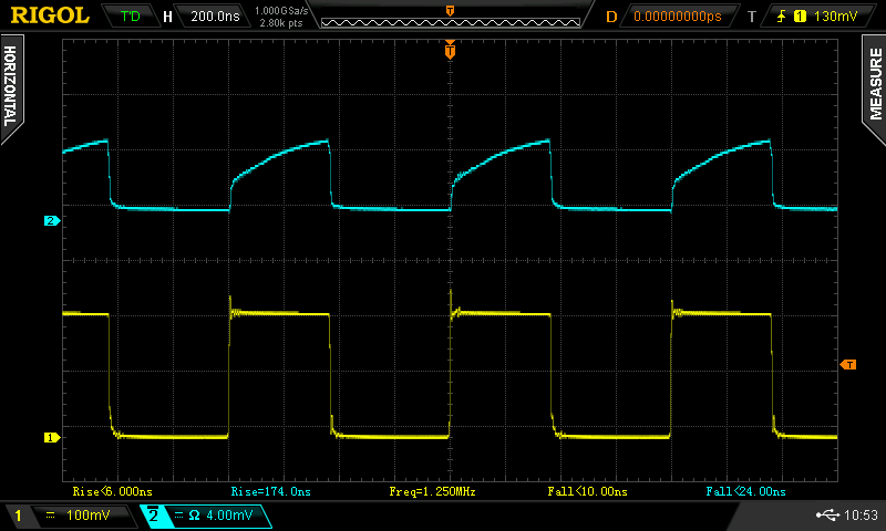
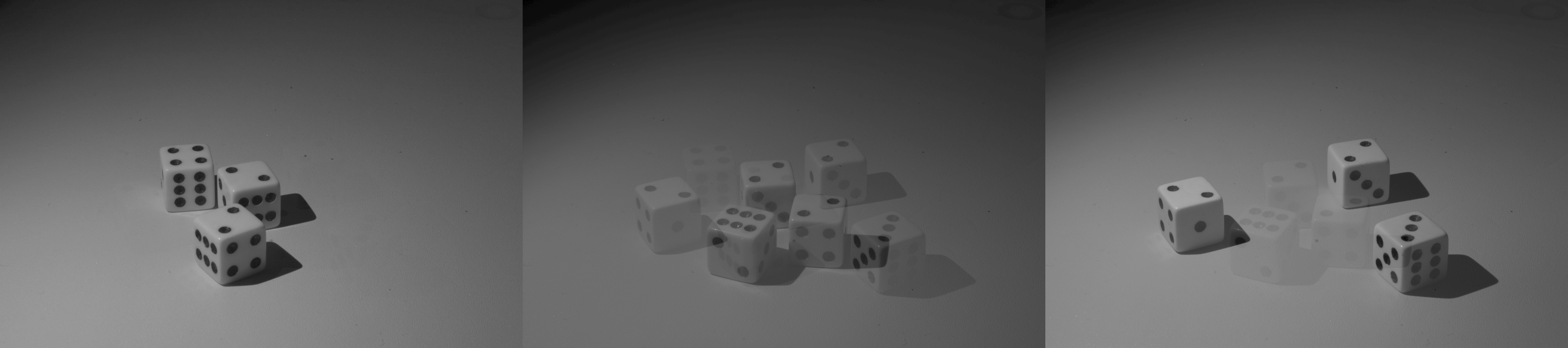
In testing these photodiode circuits, I observed some very odd behavior I haven't seen addressed anywhere. Maybe a reader will recognize what I'm seeing. I've seen this to some extent with each of the diodes I tried in this circuit. Here's the deal - the waveform output from the detector depends on how much of the photodiode is illuminated. I've read that you want to keep the diode evenly illuminated to maintain a linear response - over-illuminated regions can develop a local forward bias that distorts the signal. Here's what happens with a fully illuminated diode (left), partially illuminated diode (middle), and slightly illuminated diode (right). The vertical scale has been changed to keep the waveforms visible - the partially illuminated versions have an understandably lower amplitude.
![]()
![]()
![]()
I can't even explain the sloped response for the fully illuminated diode. At first, I thought maybe the bypass cap was too small and the bias supply was sagging, but probing that point showed no significant droop. I also tried adding some neutral density filters in the beam, thinking it might be the total brightness instead of the illuminated diode area, but the results were the same. The overall behavior reminds me a little of scope calibration - you can tune the waveform by moving the detector slightly off axis to get a nice square wave (which is what I did for the second image). Any clues?
EDIT 20161113
Another clue. The effect only seems to happen in one direction on the diode. The chip is rectangular:
![]()
With the laser moved on the long axis, the waveform doesn't change shape dramatically, except in amplitude. Smaller amplitudes do seem to have a little less "cusp" to them.
However, when the beam is moved in the short axis, the waveform changes shape dramatically. This must have something to do with the terminals being on that axis.
I hadn't noticed the directionality before, and when I went to test it again, I couldn't change the waveform shape like before - then I rotated the detector, and it "worked" again.
To David's point (below) about saturation, the peak voltage measured during the pulse is around 28 mV. Across a 25-ohm load, that's 1.1 mA of current. Is that saturated? It sounds large for a 2.9 mm^2 diode.
Bizarrely, similar diodes seem to cost around $50 each on Digikey. I ebayed these for $1.50 each. Huzzah for ebay! Also note that the $1 BPW34 is almost as good.
-
Boostrapping Lights and Sensors
11/11/2016 at 21:04 • 0 commentsSo, part of this project will involve creating very fast light pulses (the photo-flashes), and part will be detecting fast optical pulses (the milk drop and bullet detecting photo-gates). The two, of course, are related in that a fast optical pulse generator can be used to test a detector and vice versa. So, it seems reasonable to develop some test circuits on both sides - generating and detecting brief pulses of light. My first step was to build a fast laser pulser, shown here and described below. But how to test it?
![]()
I happened to have a head start on the detector side. A while ago (2009), I got lucky and found a 1 GHz avalanche photodiode module on ebay. The seller claimed it was a Hammamatsu C5658, which I have found little reason to doubt, except that it's mounted in a custom enclosure that was removed from some larger piece of equipment. It has proven very useful over the years for measuring optical devices, and I even breadboarded a LIDAR sensor with it at one point (it wouldn't be cost-effective). The module runs on 12V and has a 50-ohm output into an SMA connector - you can just hook it right to an oscilloscope or spectrum analyzer. This forms the bottom rung of my bootstrap ladder.
But, I realize that this module is going to stop working someday, and I don't have the resources to buy a new one. It would also be nice to come up with a simple design for a sensor anyone wanting to experiment with fast light pulses can build. Since the pulses I'm concerned with are very bright, most of the subtleties of photodiode amplifiers and their noise characteristics can be happily ignored. But, to verify the detector, I need a known fast light pulser - the second bootstrap.
A Simple Pulser
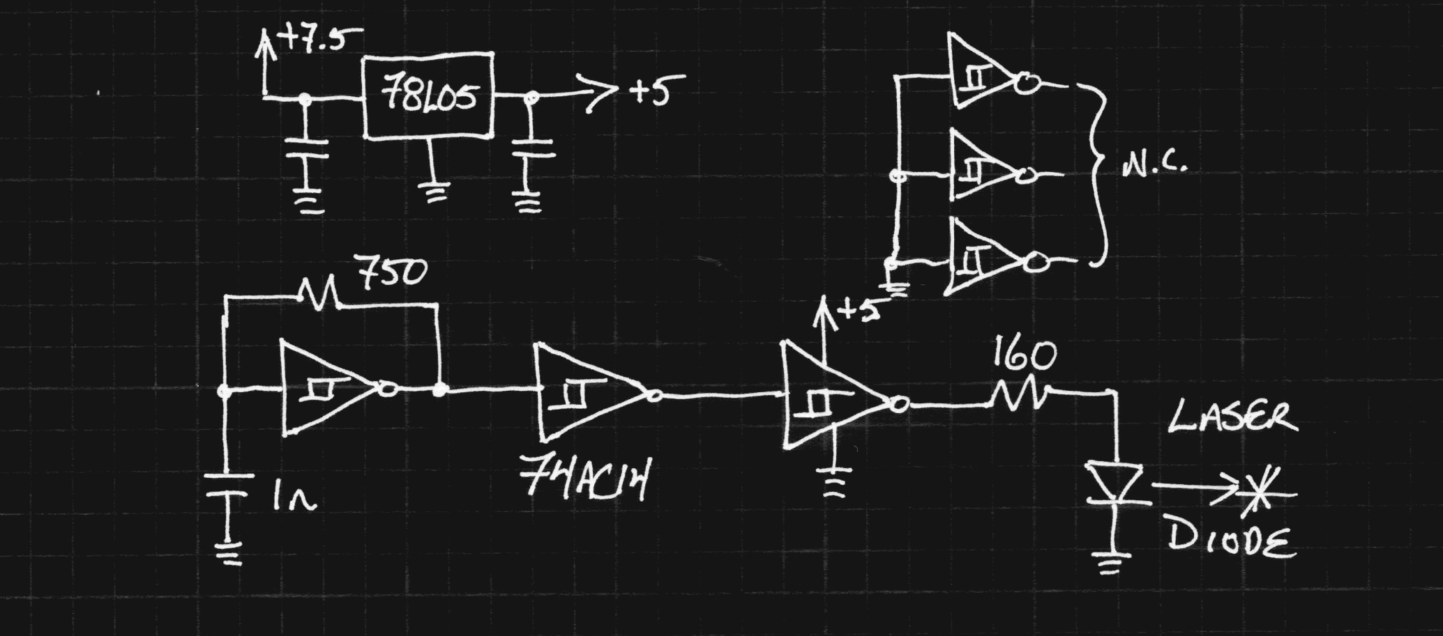
Here's the quick circuit I knocked together. It uses a 74AC14 Schmitt trigger inverter as a a 1.25 MHz relaxation oscillator buffered through two more gates before driving an inexpensive and largely undocumented Ebay red laser diode. I have previously torn down and tested these diodes to determine their lasing threshold (about 10 mA) and damage threshold (less than 20 mA seems OK).
![]()
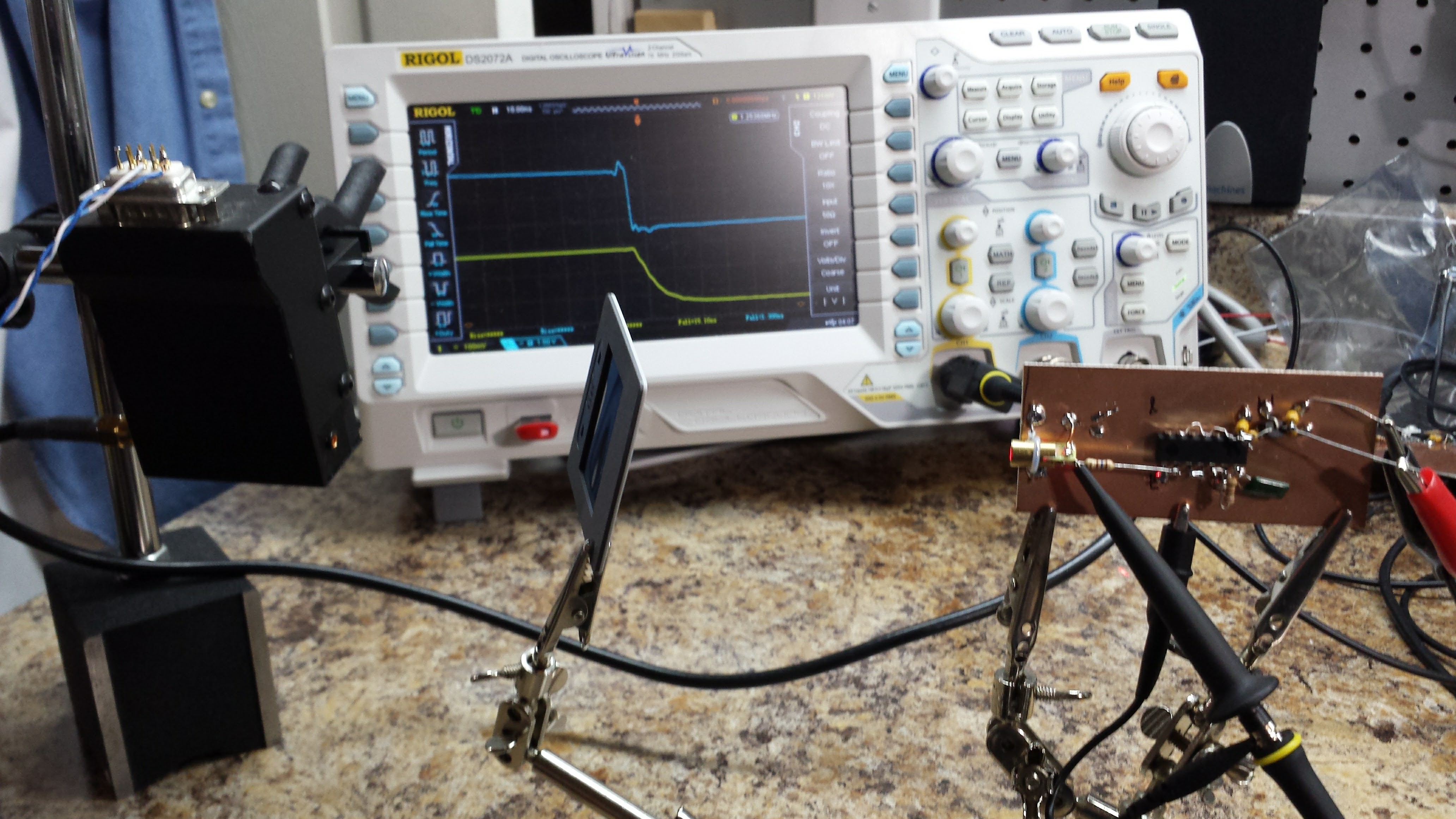
Here's how it was tested against the purportedly Hammamatsu APD module (the black box on the left). I inserted various neutral density filters in the beam to ensure the detector was operating linearly.
![]()
The diode drive, measured at the diode/resistor junction, is shown in the yellow trace, while the received light pulses are shown in cyan. The oscillation frequency is 1.255 MHz. I bought that "70" MHz scope with Hackaday Prize money (Thank you!!!)
![]()
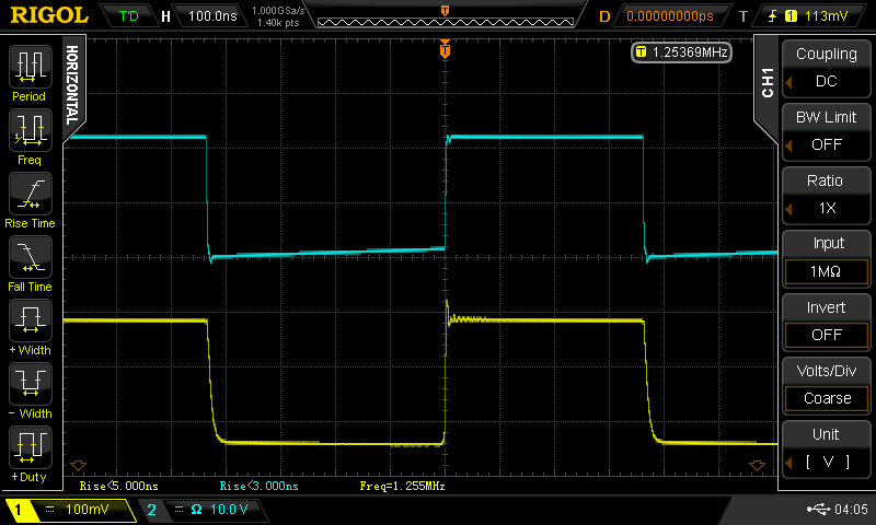
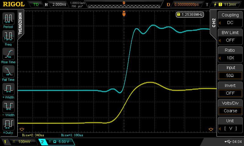
Here is the leading edge zoomed-in. Although the voltage at the laser's anode shows a rise-time of 2.34 ns, the detected light output reads 1.18 ns. I believe this may be due to the lasing threshold squaring up the edge (does anyone know for sure?). But, this is being measured on a 300 MHz scope coupled to 1 GHz APD module, with a combined rise time of around 1.2 ns, so the laser rise time may be significantly shorter. I also got lazy with the probing and just used the regular ground lead (on the yellow trace), so the electrical measuement may not be that accurate. In any case, the light pulse seems more than fast enough for testing the photogates I need to design.
![]()
Here's a measurement of the fall time. The driving waveform is pretty slow here (15.5 ns), but the lasing threshold appears to help us out again, speeding the optical fall time to a respectable 2.9 ns.
![]()
A Simple Detector
I put together a quick and easy photodiode probe ignoring the two best pieces of advice about them: always use reverse bias, and never just connect them across a 50-ohm resistor. In most situations, you really need to follow the rules, but with an excess of optical power, you can get away with the 50-ohm thing, and I'll take the hit on speed for omitting the bias. Here's the schematic:
![]()
and a picture of the unit:
![]()
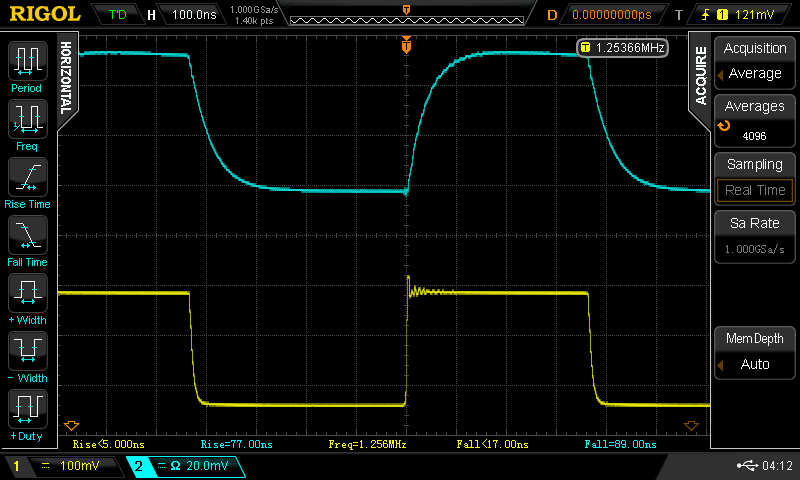
I bought some cheap RG174 BNC cables on Ebay to sacrifice in this way. They won't win any awards for low reflections, but they fit on the scope. Double-terminating them (50 ohms on both ends) helps squash reflections, but it's not really necessary at the speed of this detector. I tested the detector using the fast laser pulser - another rung on the ladder! Here's the result:
![]()
It's not great, showing 77 ns rise-times and 89 ns fall-times. This can undoubtedly be improved by applying reverse bias and/or using a faster diode. On the other hand, it's not bad for a cheap photodiode. I have a sample of BPX61 and MTD5010W diodes (20 and 3.5 ns rise-time specs, respectively) to make some faster probes (including reverse bias provided by a pair of 9V batteries). I'll document the results in a subsequent log.
Even if the performance of this probe isn't stellar, it would still be fine for measuring the relatively long 1 us flashes I have in mind.
-
Human Timeframe Tests (De-ghosting)
11/11/2016 at 03:24 • 0 commentsThe goal for this experiment was to prove that the frame-separation and ghost-correction algorithm works. Here's the test image as taken with a DSLR. The camera exposure time (shutter open) was 15 seconds, consisting of a 4 second red flash, three seconds for me to re-arrange the dice in the dark, a 1 second blue flash, another re-arrangement, and a 1-second green flash. I know from using this camera for astrophotography that it has poor red sensitivity (it's practically blind to the H-alpha line at 656nm), so I used more red light.
![]()
As you can see, the image is a jumble of the three scenes. These scenes won't make a particularly exciting animation, but should prove that the algorithm can work. The problem, of course, is cross-sensitivity between the r, g, and b pixels in the camera sensor and the r, g, and b LEDs - each pixel sees all three LEDs to some degree, resulting in ghosts when you try to separate the frames.
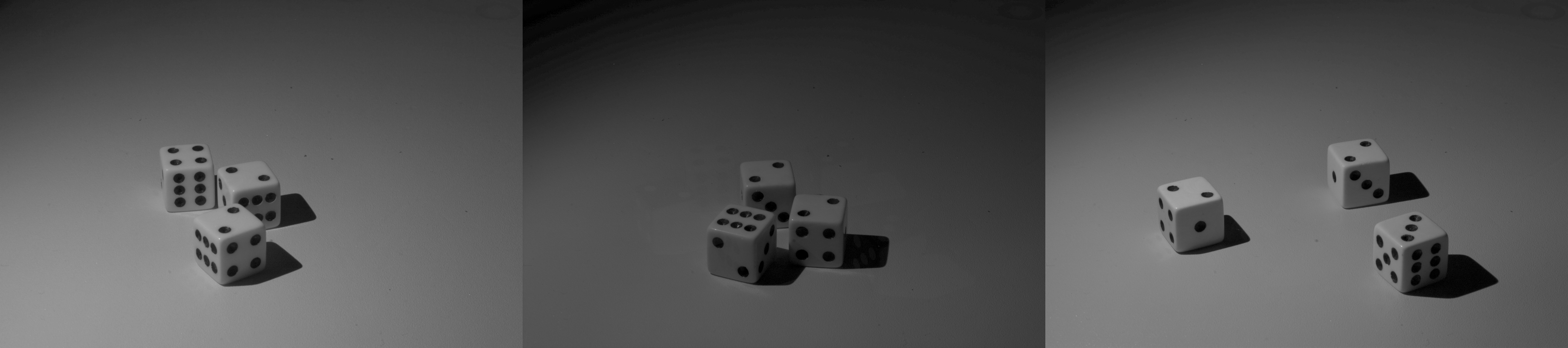
Here are the raw red, green, and blue channels of the image (left, center, and right, respectively). You can clearly see the ghosting, especially in the green and blue images - in fact, in the green image, it's difficult to tell which dice are the ghosts! It's present in the red, too, but you really have to look for it.
![]()
Now, here are the corrected images with the ghost-correction algorithm applied:
![]()
You can still see some minor ghosting in the green channel (ghosts of ghosts?), but overall, the images are greatly improved - they'd certainly be good enough to make a short animation with, assuming they had been taken of a moving object. There is also some scaling issue with my calibration algorithm that has caused the green image to darken, but if I can't figure out the "correct" way to fix this, I can always manually adjust the image brightnesses to match (with very little guilt).
Overall, I'm pretty excited by this result. I knew the math worked out, but to see it work so well in practice is very satisfying
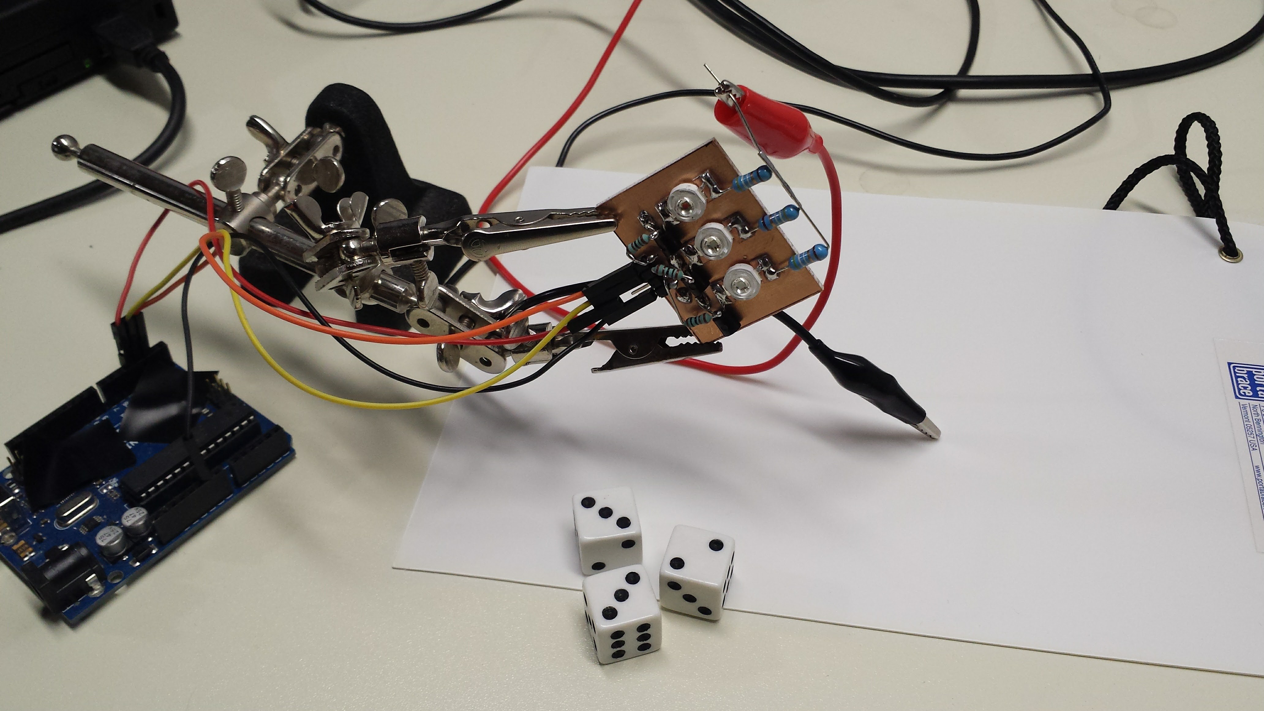
Here's the simple setup I used to capture the test images:
![]()
Ghost-Correction Algorithm
Those not interested in the mathematical details can stop reading now :-)
I used this simple model for image formation:
Where I is any particular pixel in the RGB image, M is a 3x3 matrix of sensitivities for the camera pixels vs the LEDs, and S is a vector representing the brightness of that particular pixel in the three scenes. You can write this out in terms of the components:
We measure I with the camera. If we have an estimate for M, we can use it to re-construct the individual components of S, in other words, the pixel values in the three scenes, by applying the inverse matrix:
To estimate M, three separate images were taken of a photographic white balance card, one illuminated with each of the LEDs:
![]()
I chose only pixels with maximum components between 100 and 254 for calibration. This eliminates much of the noise. Each image gives an estimate for one column of the matrix M. For example, with the red image, we have:
so, we can estimate the first column of M by:
We don't really know Sr, but since we're only really interested in the ratios of the color sensitivity, we can arbitrarily set Sr to 1 (likewise with Sg and Sb). Of course, this is where my image brightness issue comes from, but it doesn't seem like a huge problem. With the three images, we can estimate the three columns of M, and then invert the matrix for the correction algorithm. If the matrix ends up singular, you've got some bad data or a really terrible camera...
As an example, here's the estimated matrix M for the test images in this log:
You can see the cross-sensitivities in the off-diagonal components, especially between the green and blue channels.
Caveats
If you try this algorithm, make sure you have linear RGB pixel values. You probably don't. Trying this algorithm with images in a gamma-corrected color space like sRGB is a waste of time; it's just not going to work well at all. If you have to, you can apply the inverse gamma transformation to your image to get back into a linear space (at the cost of some precision). A better approach is to capture images in raw mode, if you have a capable camera. I captured these images with a Canon EOS 10D (that I've been using since 2003) which has a 12-bit ADC. I used Dave Coffin's outstanding dcraw program to decode the RAW image format into a linear space. Unfortunately, the python library I am using (PIL) doesn't support 16-bit component images, so I'm stuck in 8-bit precision.
I'll probably end up re-writing this code in C++ anyway, at which point I can use my old libraries for 16-bit images. I am anxious to see if the added precision improves the correction algorithm.
Another trick is to avoid mixing the channels during de-mosaicing. The pixels inside the camera are typically arranged in a Bayer pattern, which interleaves separate red, green, and blue sensitive pixels. To create an image with all three components at every pixel, software within the camera interpolates the missing values. In doing so, the three frames in my system are irreversibly mixed. Luckily, dcraw has an option to interpolate the color channels independently, which greatly improves the result.
The command line I used to extract the raw images from the CRW files from the camera was:
dcraw -W -g 1 1 -o 0 -f
EDIT 20161111
As I was falling asleep after writing this log, I realized what this algorithm means in terms of color science. I'm not a color scientist, but I've ended up dabbling in the field professionally for a long time. Anyway, multiplying by M^-1 can be seen as transforming the image into a color space where the LEDs are the three primaries. In this space, light from the red LED has the coordinates (1, 0, 0), and so on. This interpretation might provide clues about a more robust way to estimate M.
You may have noticed that my test scenes are of black-and-white objects. This eliminates some thorny issues. Colored objects will reflect the LED lights differently, causing objects which change their appearance in the three frames. Due to the bandwidth spread of the LED output, colored objects will also degrade the performance of ghost correction. Single-wavelength sources (hmmm, lasers) wouldn't have this issue. Additionally, any fluorescence in the objects (especially an issue for the blue LED) will cause uncorrectable ghosting. Even within these limitations, I think some interesting brief animations can be captured.
Bullet Movies
Using red, green, and blue LEDs to capture short movies of very fast objects