-
New release
04/10/2022 at 17:26 • 0 commentsOn Green BMS Github Repository, the new release is available.
After about 10 months of use, I improved the final charging phase, refining the balance of the cells and the use of the current limiter.
Here is a description of the changes:Control Unit Software:
Ver. 3.s.2.02 date 10/04/2022
Version notes:
- Modfied Pack charged status reset, using the SOC percentage: the charge enable returns when the SOC is below 99%.- Modified Balance relay code (current limiter command): in the final part of charging, when all the cells are close to the balance value, current limitation is forced.
-
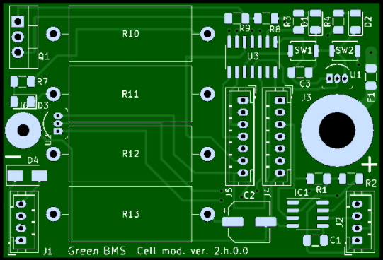
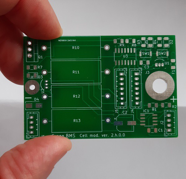
PCB assembly and where to buy
12/09/2021 at 15:55 • 0 commentsFor my BMS I decided to buy the PCBs online and to assemble them by myself.
The PCB online supplier I have chosen is PCBway.
![]()
After several successful orders I can confirm that the quality of the cards is excellent.
Furthermore, the service is simple and fast: with a few clicks you can easily place your order, attaching the Gerber file.![]()
![]()
It is also possible to order the boards already assembled by attaching the BOM (bill of materials).The assistance service is excellent: there is always a person available to answer your technical and commercial questions.
You can sign up to PCBway at the following link: https://www.pcbway.com/setinvite.aspx?inviteid=436793
You can buy Green BMS PCBs at the following links:
-
Applications and future improvements
10/26/2021 at 13:15 • 0 commentsLithium batteries, with their chemical evolutions, are increasingly used in our life.
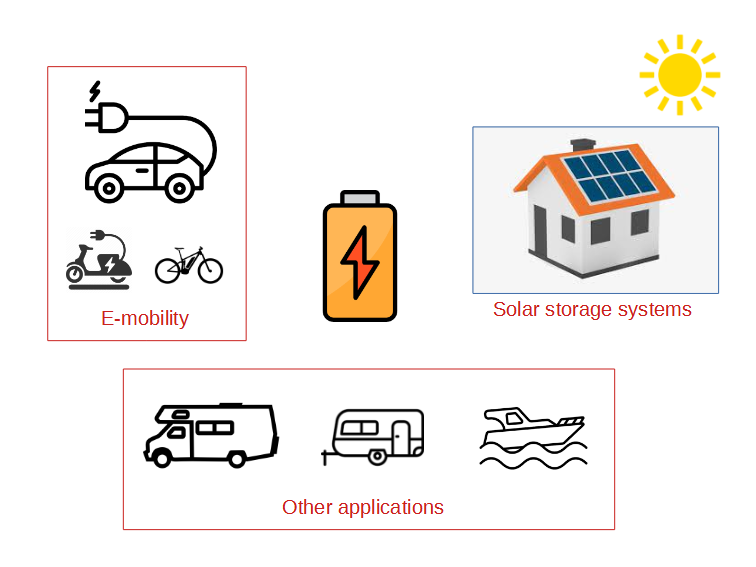
The main applications of powerful battery packs are electric mobility and domestic energy storage for photovoltaic panels.
These technologies are improving our lives by helping us to reduce the problem of pollution and will be used more and more in the future.
![]()
All lithium batteries need a BMS ... so the BMS is an essential component for an eco-sustainable future!
Green BMS was born for fun, but it can be an interesting project, because it is simple, modular and ... open!
Anyone can make it to manage their own DIY battery system.
Anyone can improve it, customize it and adapt it to their needs.
![]()
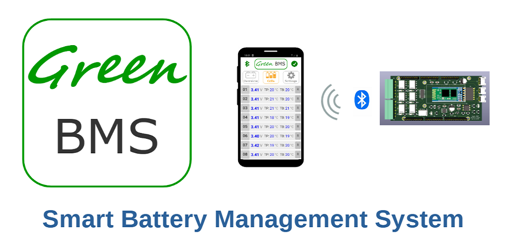
I believe that the great added value of Green BMS is to be Smart with the Android application: there are few open source projects of this type that include a fully open Android application.
And what about the weak points?
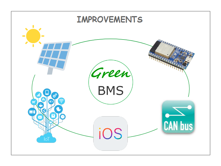
There are many improvements that can be made to the project, here are some examples:
Cell Module:
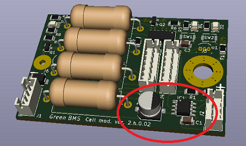
- Reduce the size: I’d like to modify power resistors in order to reduce each PCB size to adapt it to smaller cells
- Improve the balancing circuit in order to move mosfet protection out from controller logics
- Realize an optional module board that manages more cells at time (for small battery packs).
- Find solutions to make it cheaper
Control Unit:
- Base the Control Unit on a smaller, lower consumption microcontroller (ESP32)
- Increase the number of cells to manage
- Add new interfaces with most popular chargers, using canbus and pwm signals
- Add Low temperature protection
- Add IOT functionality (I'm already working on this …)
Smartphone application:
- Create it for IOS phones
- Add solar panel management
![]()
... and other important improvements that I have in mind, but which I do not want to anticipate for the moment …
I am proud of this project and happy to share it with the world!
Go green with Green BMS!
-
Design challenge n.15: Pull-up resistors on I2c bus
10/25/2021 at 17:14 • 0 commentsThe last difficulty I had to overcome came when the project was finished.
While charging the battery, noises from the charger caused communication losses.
The good news was that the system went into protection, blocking the charge, and that the system reset itself and resumed its normal functions.
But the bad news was that the I2C network was too sensitive to noises.
I immediately thought about the filtering problems, questioning the size of the capacitors I installed in the boards.
![]()
By researching the typical problems of an I2c network, I realized that I was neglecting the pull-up resistors: with the increase of the connected bus cards (in my case 16), the capacity of the line increased.
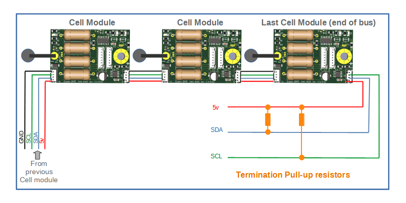
So I tried to add the pull-up resistors in the free I2c connector on the last bus board, making a termination connector
In my case I did this: I removed power from the bus and measured the resistance value between 5v and SDA (and 5v-SCL). I measured 10 Kohm.
After that I applied a Resistance of 1.8 k (parallel of 3.3K and 3.9K) in order to bring the total pull-up resistor of the bus = 1,5 Kohm.
![]()
Maybe the method I used is a bit empirical ...
For those who have time, a more scientific method is to connect with an oscilloscope, view the signal and use a trimmer to find the suitable resistance.
In any case, the empirical method worked well: the network no longer crashed due to the noise of the charger!
-
Design challenge n.14: data exchange management
10/24/2021 at 18:10 • 0 commentsA complicated challenge of this project was the management of data exchange in the installed networks.
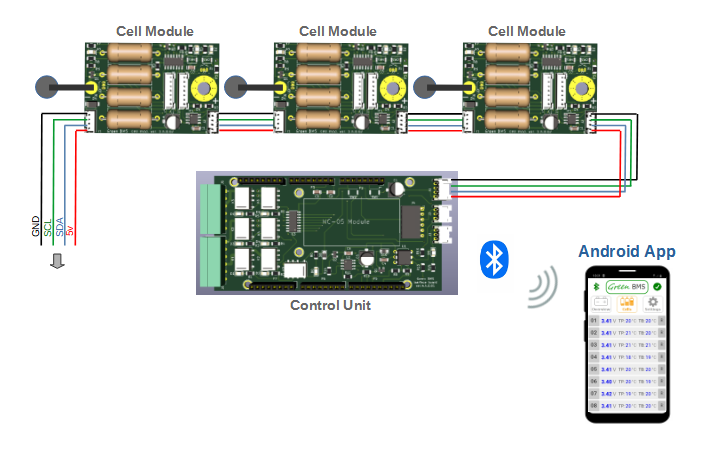
The I2c communication with the cells is the main network (always alive), the Bluetooth communication with Android app is the secondary network, that is alive only when user connects with the App: how to manage data exchange?
![]()
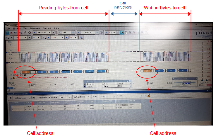
The goal was to be able to read and write data with the maximum number of cells (40) within 5 seconds, so I had in theory 125ms per cell.
I analyzed i2c communication with my picoscope:
![]()
So I immediately thought of using a fixed timing with which to read and write the data on each cell.
But this setting proved risky for a simple reason: when I enabled Bluetooth communication with the Android application, problems arose due to the variable and unpredictable length of this data exchange.
In practice, cell writing/readings steps were periodically skipped, with loss of synchrony.
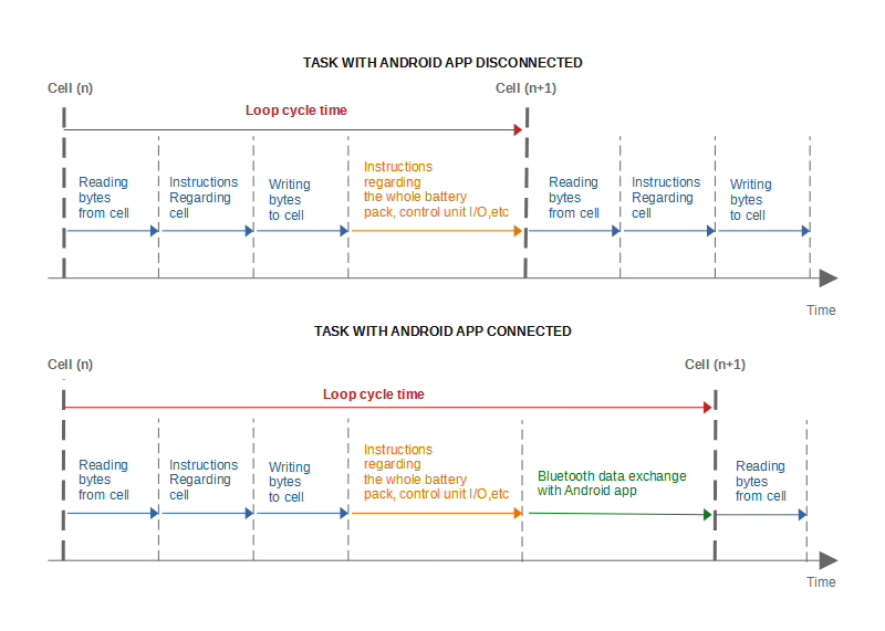
Not being able to predict the duration of the Bluetooth data exchange, I therefore decided to leave the idea of a fixed timing and work sequentially, letting each step begin with the end of the previous one.
In summary I organized the task in this way:
![]()
This solution guaranteed the execution of each step without losses.
To keep the Bluetooth data exchange time below an acceptable value (about 20 ms), I split the exchange data to be received / sent into the various loops.
-
Design Challenge n.13: Android app
10/23/2021 at 07:43 • 0 commentsAt the beginning of the project, I was thinking of connecting a touchscreen display as a human-machine interface, which is a typical solution used by many.
But immediately I asked myself: how many times does the user of a BMS need to look at the display to check the status of the battery cells?
Wouldn't it be better to think of an occasional interface, to be used only when needed, occupying the necessary resources only on these few occasions?
This is why I thought of an application on a smartphone: who doesn't have a smartphone?
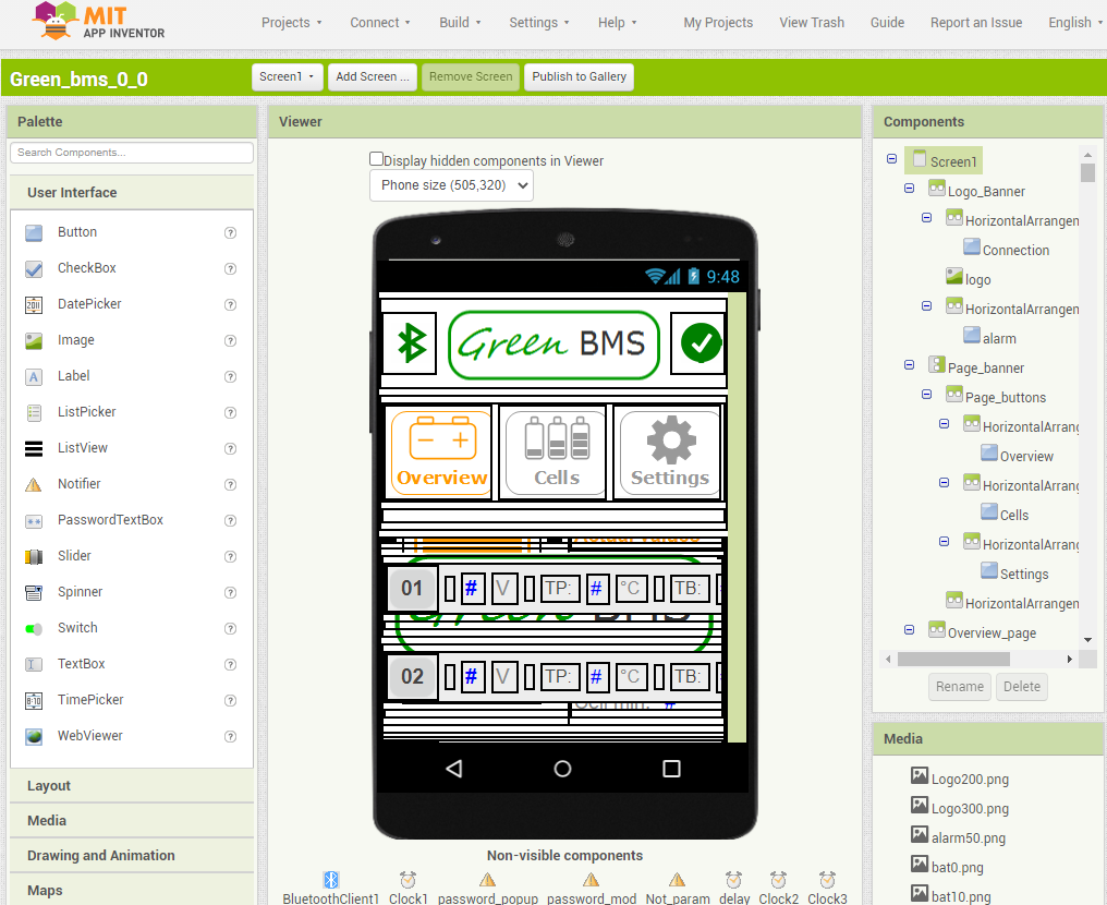
After a lot of online research, I decided to use Mit App Inventor, an open source online application.
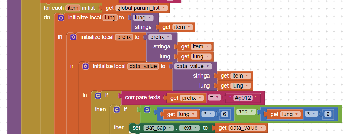
![]()
Developing a smartphone application was the absolute novelty for me in this project.
I spent a lot of time learning the various programming rules and especially data exchange with Arduino.
![]()
The main difficulties I had to overcome were 2:
1. The management of unwanted characters that often pass through the Bluetooth network which forced me to use char control instructions
2. The compilation process of the Mit App Inventor project.
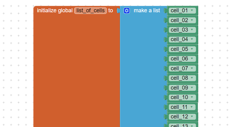
A typical mistake that beginners (like me) make is to use too many programming blocks: this crashes the project at compile time.
![]()
Researching through the Mit App inventor community, I learned to significantly reduce blocks using the Lists of objects, calling each of them through the For Loop.
![]()
This solved the problem!
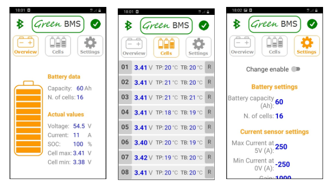
I had also to work a lot on the graphic look. I thought of a layout that could be simple and practical, with a few pages containing only the information necessary for the user ... I hope I succeeded …
![]()
-
Design challenge n.12: Control Unit Interfaces
10/22/2021 at 09:52 • 0 commentsThe main function of a BMS is to give consent to charge or discharge the battery.
To make green BMS as versatile as possible, in order to cover many types of applications with different powers, I made this choice: I decided to use relays.
With the free voltage contacts of the relays, the user can control an additional protection circuits best suited to his needs.
Important: the charge and discharge protection relays are used with NO (normally open) contacts energized to close the contact: this is a safety feature because in the event of a loss of power on the relay coil, the contacts open.
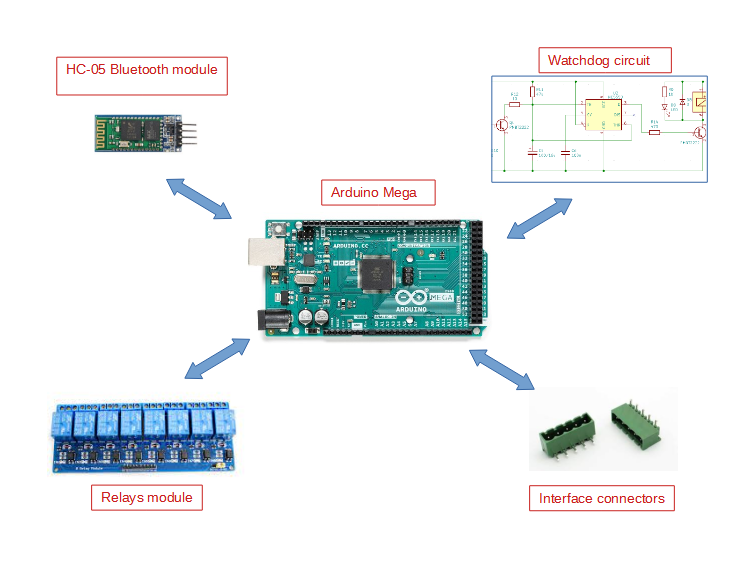
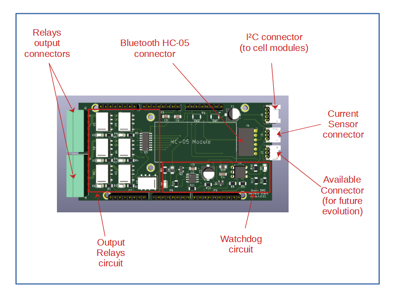
The Control Unit therefore consists of the following components:
![]()
How to combine them all together in the most compact way possible?
Kicad and the open source community gave me a great idea.
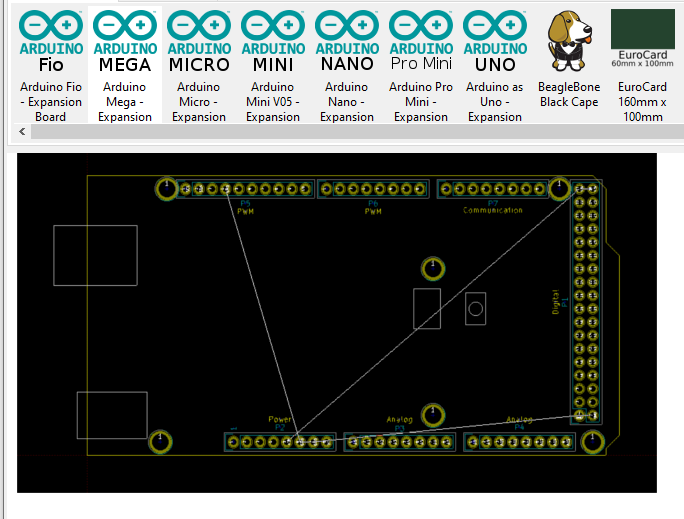
In fact, with Kicad various customizable models of expansion cards are already available, including the arduino Mega expansion!
![]()
So I tried to enclose all the components of the Control Unit in a single board called “Interface board” to be plugged onto the Arduino Mega, here is the result:
![]()
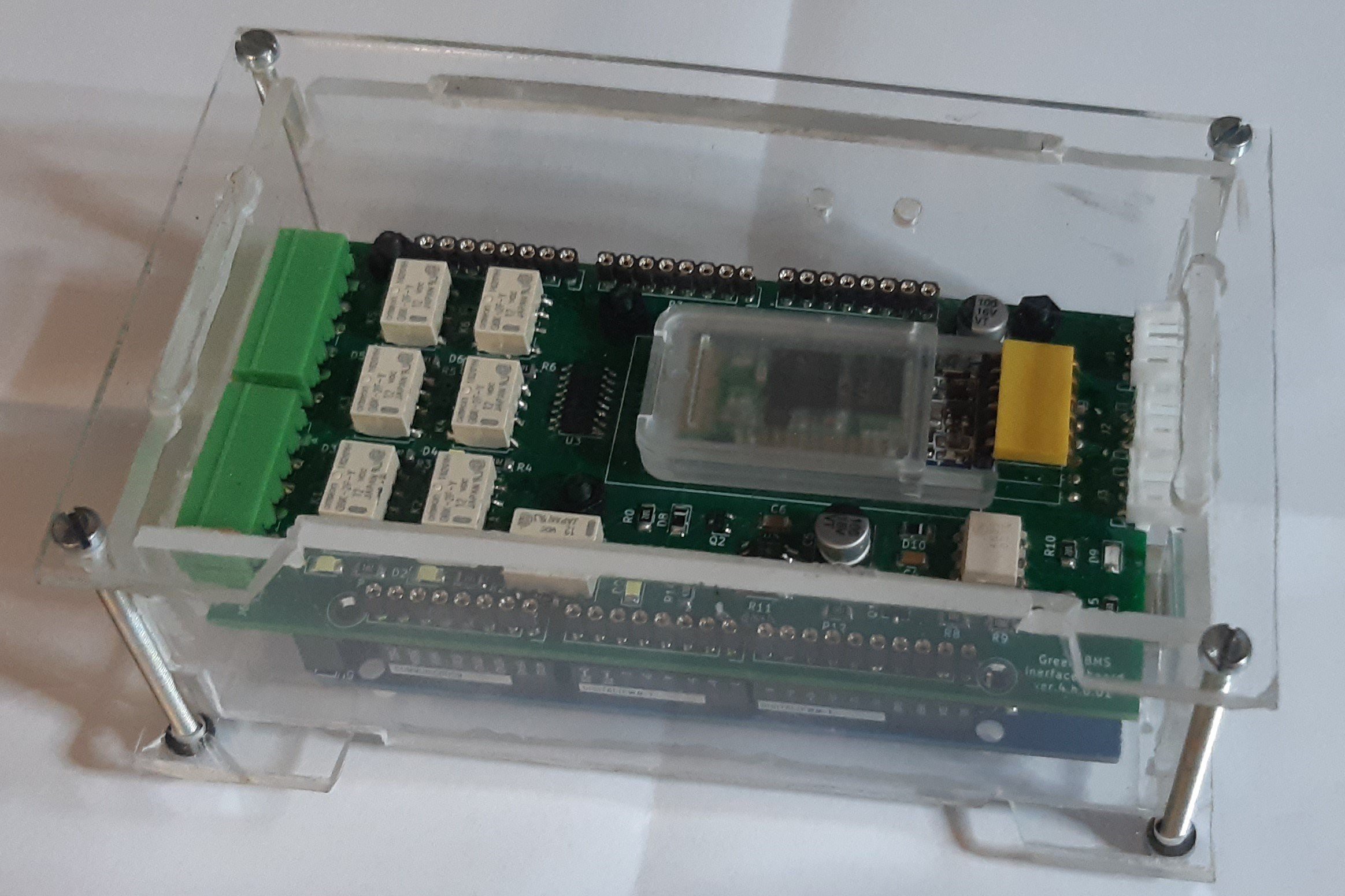
After that it was easy to design and build the case:
![]()
-
Design challenge n.11: Watchdog
10/21/2021 at 09:56 • 0 commentsMicrocontrollers can crash.
This can happen for sketch mistakes, but also for failures in the microcontroller itself... so it can happen.
When this happens, the outputs remain frozen at the last value and this led me to an important question:
What would happen if the Arduino Mega crashes while charging the battery, with the charge consent output active?
The risk is to lose the protection of the BMS due to overvoltage of the cells, with bad consequences on the battery pack.
For this reason I have inserted 2 levels of watchdog control:
1) Software: in case of crash, the microcontroller is restarted, but this protection for me wasn’t enough, so I added the watchdog ...
2) Hardware: I made a circuit independent from the microcontroller, using the NE555 integrated circuit.
Here is the scheme:
![]()
It works like this:
Arduino Mega provides a digital output called "Heartbeat". It is a square wave with a period of 500 ms.
When this signal is present (software OK), the watchdog circuit closes the relay "K0" which has the function of supplying all the relays including those for enabling the charge and discharge.
When the Heartbit signal is blocked , at a high logic level or at a low logic level (software crash), after the delay time of 5 seconds (t = 1,1* R11*C5) the relay K0 is disconnected opening relays supply.
This solution satisfied me, because with few components, I made the system safer in case of Arduino crash.
-
Design challenge n.10: Project development
10/20/2021 at 09:57 • 0 commentsWith my experience I have learned that, before starting with the development of a project, it is advisable to dedicate some time to create a simulation platform, in order to have the whole system at hand, with the various interconnected components. It is not a waste of time!
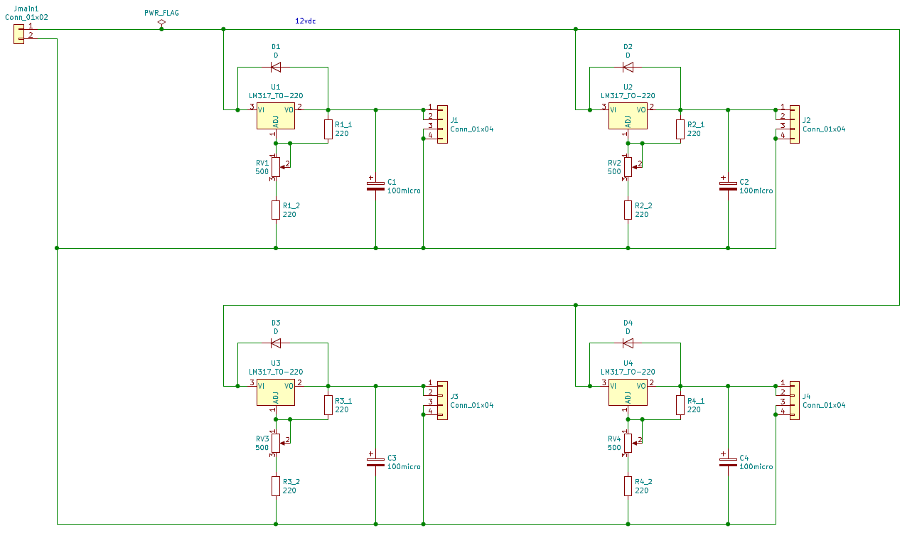
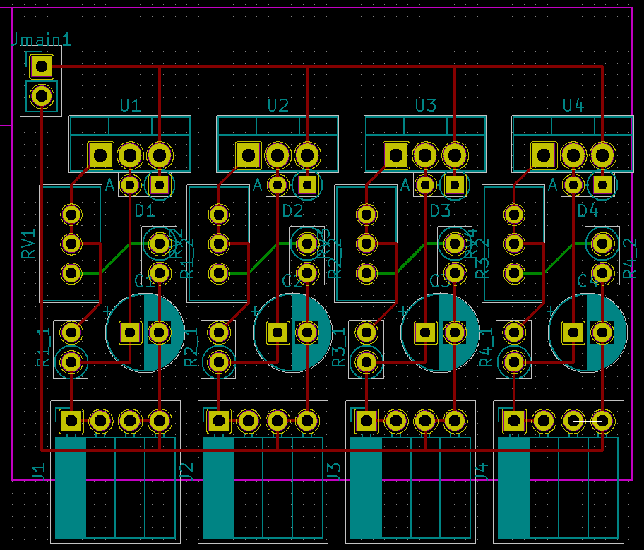
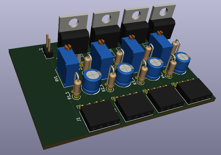
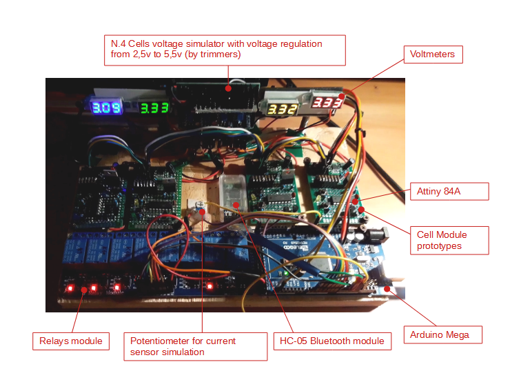
To develop the project, I made a “portable” 4 cells BMS simulator.
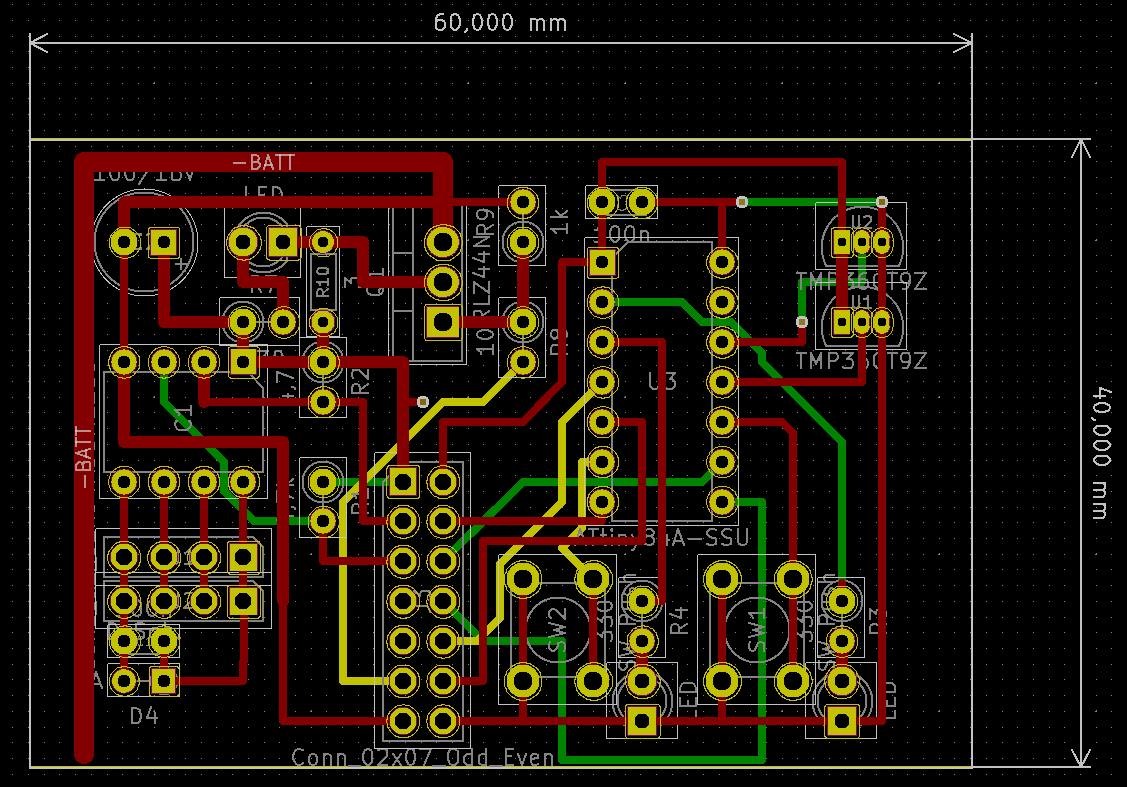
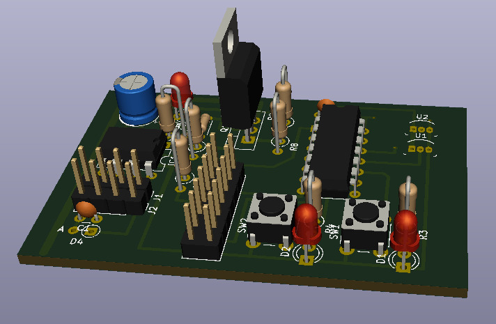
First I designed with Kicad and made the prototype of the cell module (without balance resistors), on a matrix board, using dip through hole components:
![]()
![]()
After that, I thought of a way to simulate the battery cells, varying the voltage of each to my liking.
I made a 4 set point generator using components I had:
![]()
![]()
![]()
So I assembled all the components on a wooden board...
![]()
Thanks to this prototype I was able to simulate all parts of the system and develop the software of each component including the Android app, comfortably in the warmth of my home during the winter months of last year!
-
Design challenge n.9: Arduino IDE Software functions
10/19/2021 at 10:07 • 0 commentsEvery software designer has their own way of programming, there is no single method.
My job is PLC (Programmable Logic Controller) programmer and therefore I developed my project on Arduino IDE using the methods and functions that I normally use in Ladder language.
First, I avoided using interrupts and the "delay" command: I made sure that the task always ran as smoothly as possible.
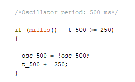
So where it was necessary to use timings, I did it via the "Millis ()" function, here is an example:
![]()
I have also created 2 typical PLC functions that are very important to me:
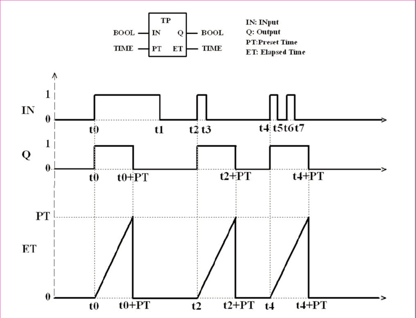
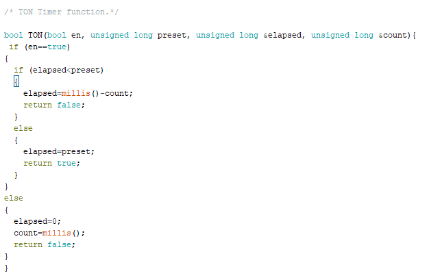
- TON = timer on
![]()
The function I created to use the TON is this:
![]()
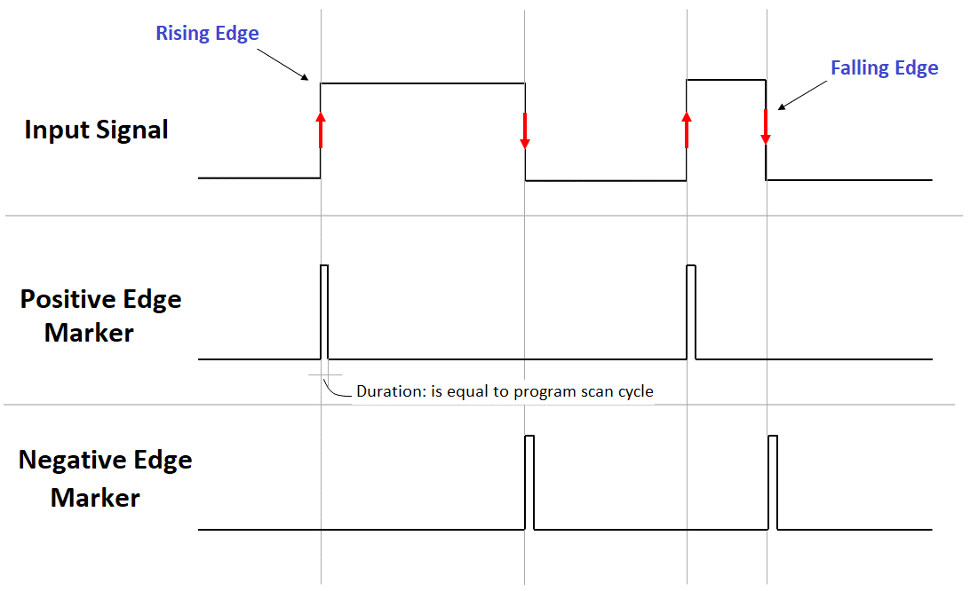
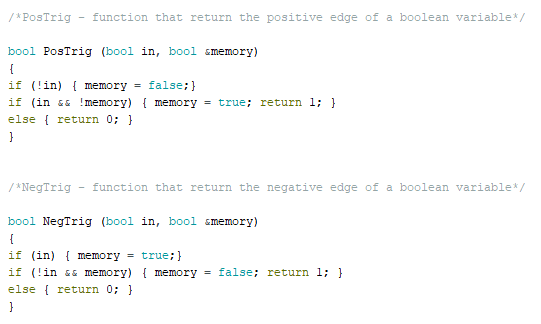
2. Positive and negative edges
![]()
The functions to use edges are this:
![]()
These functions, added to others that I have created, have allowed me to develop Attiny and Mega sketches as I like!!!
 Sergio Ghirardelli
