-
Design challenge n.8: temperature sensors
10/18/2021 at 10:13 • 0 commentsOne of my goals in this project was to do a temperature control on each single cell module, in order to remove the enabling for charging and discharging in case of high temperature.
First I had to choose the type of sensor.
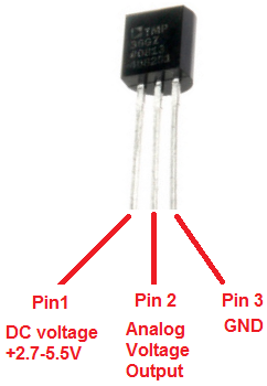
Due to the supply voltage ranges of the cell, I chose to use the TMP36 analog sensor that can be supplied between 2.7v and 5.5v.
![]()
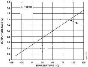
TMP36 can detect temperatures from -40 °C to 125 °C.
![]()
While I was thinking about the most suitable point of the circuit where to install the sensor, I thought about one thing:
Why not include something more in my project than other BMS's? Why not also monitor the temperature of the balancing resistors, in order to interrupt the balancing in case of exceeding a threshold set by the user?
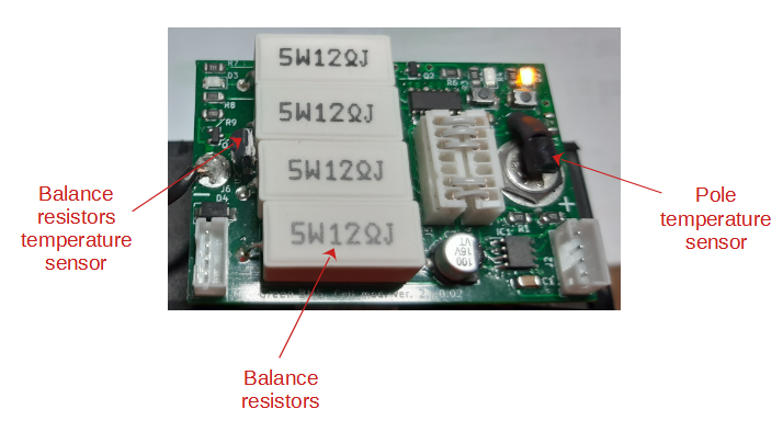
So I decided to add a second TMP36 for the resistors.
I placed the sensors like this:
![]()
To be more effective in the measurement, I fixed the sensor body with thermal glue to the point to be measured.
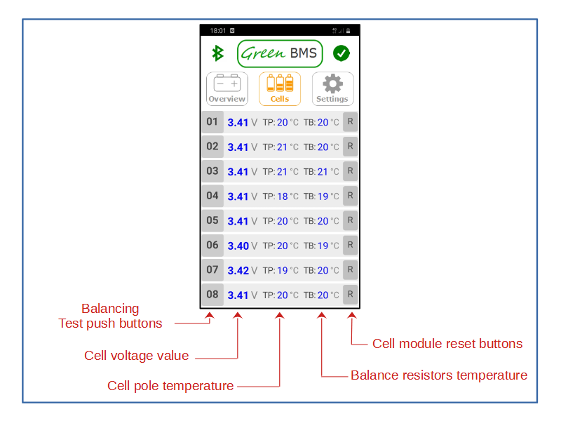
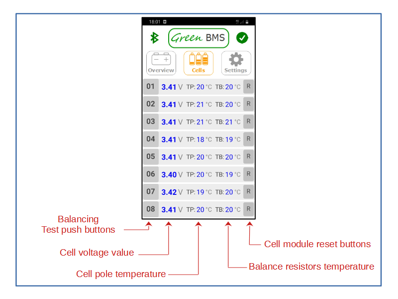
Thanks to this configuration, it is possible to monitor the temperature values of the pole (TP) and of the resistances (TB) in each cell at any time via the app.
![]()
Through the threshold parameters of high cell temperature and high balancing temperature, the user can decide above which pole temperature to remove the consent for battery charging and discharging and above which temperature of the resistors to stop balancing.
A possible improvement?
To add a Low temperature threshold parameter of the pole, below which to block the consent to charge the battery.
This thing will be done in the future evolution of the project ...
-
Design challenge n.7: the fuse voltage drop
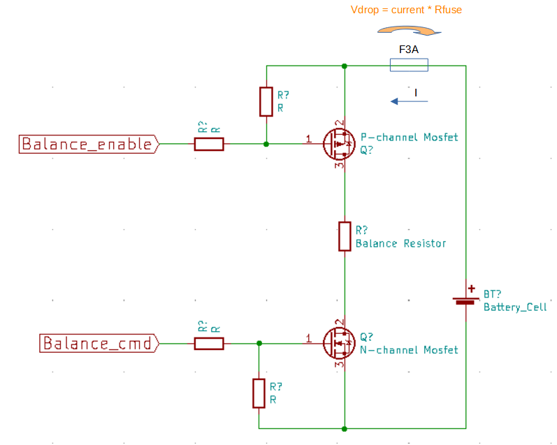
10/16/2021 at 17:25 • 0 commentsThe cell module circuit includes a 3A fuse connected immediately to the module's positive power supply.
The fuse has a very low internal resistance (about 50 mOhm)
However, this resistance becomes a problem during balancing, because the balancing current of 1A causes a voltage drop across the fuse of about 50mV.
![]()
This drop compromises the cell voltage measurement during balancing, compromising the regulation logics: because the microcontroller detects a lower voltage than the real one of the cell!
How to solve this challenge?
Could I remove the fuse? No...it could be dangerous in case of short circuit!
So I immediately tried to find a way to calculate this drop and compensate it with a mathematical formula in the software.
But this choice proved to be very complex due to the many variables involved to be managed:
different fuse resistance for each board, user variable balancing current, balancing resistors with different tolerances, different balancing voltage between Lifepo4 and Lion ... etc.
Too inaccurate: another solution had to be found.
After a few days of reasoning I had a simple thought:
I have a microcontroller that manages the balancing circuit and I have a mosfet that can switch quickly!
So why not periodically interrupt the balancing, to acquire the real voltage of the cell?
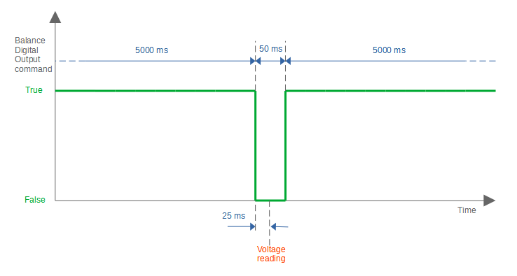
This graphic shows the logic I have implemented in the software:
![]()
Every 5000 ms the balance is stopped for 50 ms.
In the middle of this time a voltage reading is taken, which without the fuse voltage drop corresponds exactly to the real cell voltage!
I am very satisfied with this simple solution that I have found.
-
Design Challenge n.6: balance circuit mosfet N short circuit failure
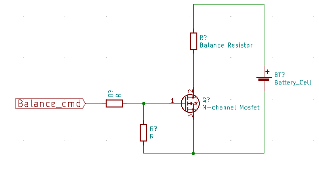
10/15/2021 at 20:55 • 0 commentsThis was the first version of the balancing circuit diagram of cell module:
![]()
The balancing command digital output (from Attiny microcontroller) drives a N-channel Logic Mosfet which closes the circuit on the balancing resistor.
I did not like this version of the circuit for this reason: in the event of a short circuit failure between the source and drain of the mosfet, the circuit would have closed the resistance on the cell, causing the risk to damage the cell by falling below the minimum voltage threshold.
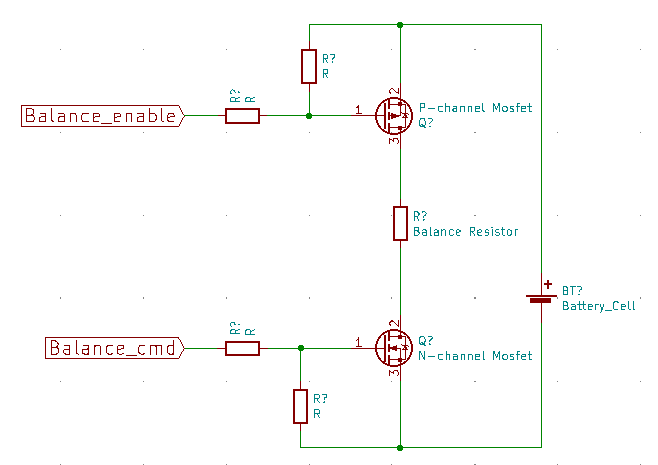
I wanted a protection for this event, so I modified the circuit like this:
![]()
I added a second P-channel Logic Mosfet on the positive power supply of the circuit, driven by another digital output of the microcontroller.
When the cell voltage is greater than 3200 mV, the balancing circuit is enabled, when it’s lower the balancing circuit is disabled.
![]()
So I protect the cell from the short circuit failure of the mosfet N, because below 3200 mV it is no longer balanced.
In the next evolution of the cell module, I decided to no longer drive the mosfet P from the microcontroller, but to use a hardware comparator circuit independent of the software of the microcontroller, in order to make the circuit even more safe.
-
Design challenge n.5: what type of balancing resistors?
10/14/2021 at 18:16 • 0 commentsMost of the low cost passive smart bms that are on the market, in my opinion they all have one limit in common: low balancing currents, from 30mA to 100mA
Anyone who has experience with lithium cells, especially with Lifepo4, knows that with use, the cells can reach differences that are really difficult to compensate with such low balancing currents...it takes many hours of balancing!
For this reason, I have chosen to make a BMS capable of balancing at 1 A.
The challenge was clearly to achieve this goal while maintaining prices, dimensions and temperatures at acceptable levels.
I chose the experimental method.
I defined the volume of the module that I would dedicate to the resistance:
(W20mm x H40mm x W10mm)
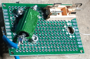
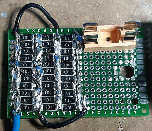
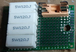
After that I compared three types of power resistor, each soldering them on their own prototype board:
1 – n.1 armored resistor 3 ohm 10W
![]()
2 – Parallel of n.33 smd resistors 100 ohm 1W: equivalent to 3 ohm
![]()
3 – parallel of n.4 cement resistors 12 ohm 5W: equivalent to 3 ohm
![]()
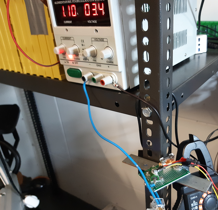
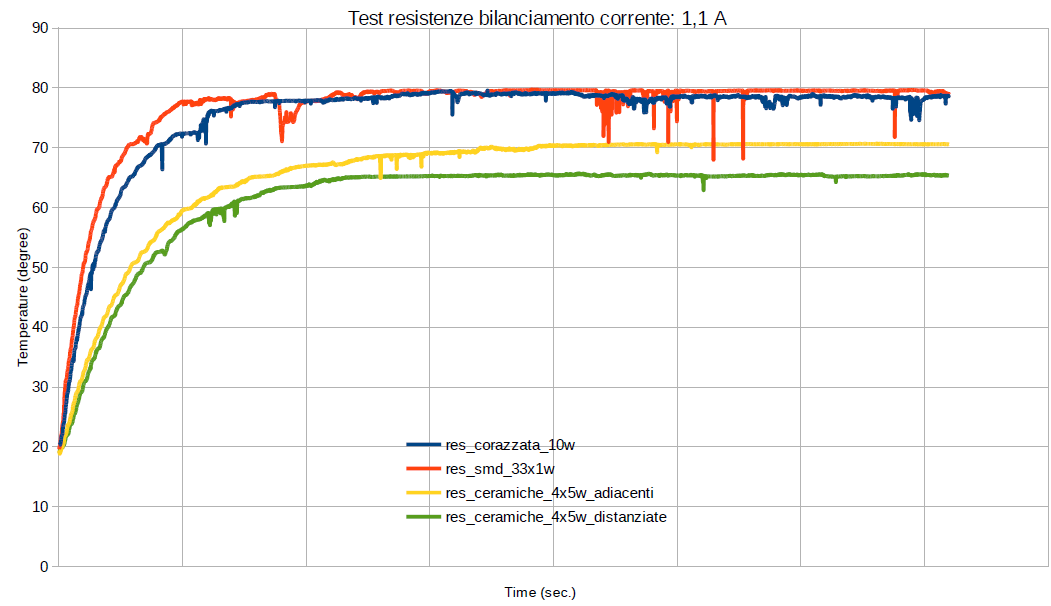
Then, under the same environmental conditions (same day, with ambient temperature: 17 °C), I applied a voltage to each of the prototypes, in order to have the same balancing current (1,1 A), for 1 hour.
![]()
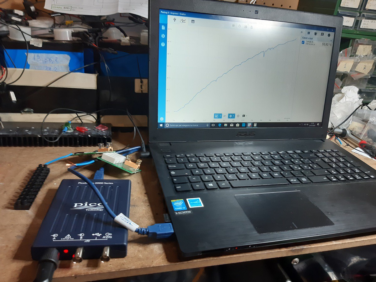
During the balancing I measured the temperature on the body of each resistor using the TMP36 chip, acquired by my Picoscope 2204A oscilloscope and I recorded its trend using the PicoLog application.
![]()
For the cement resistors I did a double test: the first test with the resistors in contact, the second test with the resistors slightly spaced from each other, in order to allow the passage of air.
This is the result:
![]()
The test shows that:
1) cement resistors heat up much more slowly and reach a temperature of about 10-15 ° lower than other types
2) spaced resistors are better than resistors in contact
3) smd and armored resistors have more or less the same behavior
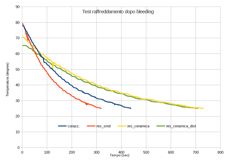
The following graphic shows temperature trend after disconnecting the power supply (return to ambient temperature).
![]()
From this measurement, it can be seen that on the other hand, smd and armored resistors have faster cooling time (5-6 minutes), while cement resistors take longer time (11 minutes).
After these tests, also considering the prices, I decided without any doubt to use the cement resistors on Green BMS cell modules.
-
Design challenge n.4: voltage measurement accuracy
10/12/2021 at 18:49 • 0 commentsAttiny84 microcontroller consents to measure the supply voltage, avoiding the use of an analog pin.
How is accurate this measurement?
In this phase of the design I made a bad discovery: connecting several controllers to the same power supply, I had different measurements, with values that differed even by 30-40 mV!
Panic…
In order to solve a situation like this, experience teaches me that we need to calmly collect the necessary data ...
So I connected 3 different attiny microcontrollers (one at a time) to my bench linear power supply, and I collected in an excel sheet the voltage measured with my multimeter and that detected by the microcontroller, for a scale from 2.6v to 5v, taking a measurement every 50 mV
![]()
I first tried to figure out if there was simply an offset to add up to compensate for the error, but I quickly saw that this was not constant.
So I created a calculation column where I reported the gain, according to the formula:
gain = V_measured (multimeter) / V_attiny (microcontroller input)
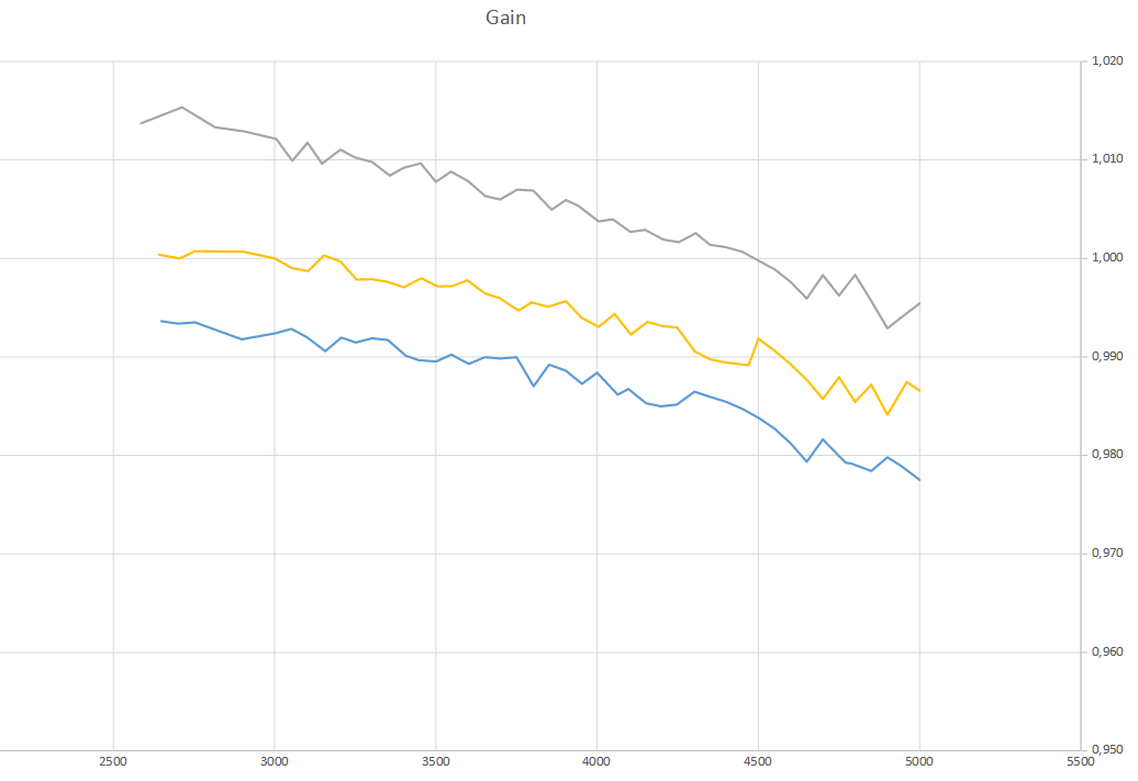
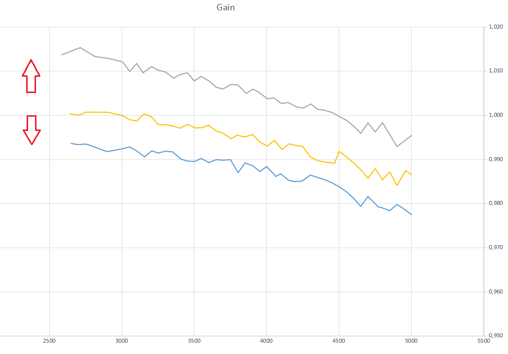
After which I reported the gains of the three modules in a graph as a function of the measured voltage, with the aim of finding a visual relationship between the gains of each module.
This is the resulting graph:
![]()
Looking at the trends, we see that the gain drops with increasing voltage, with a similar range, for all the modules. The difference seemed to be just a question of offset:
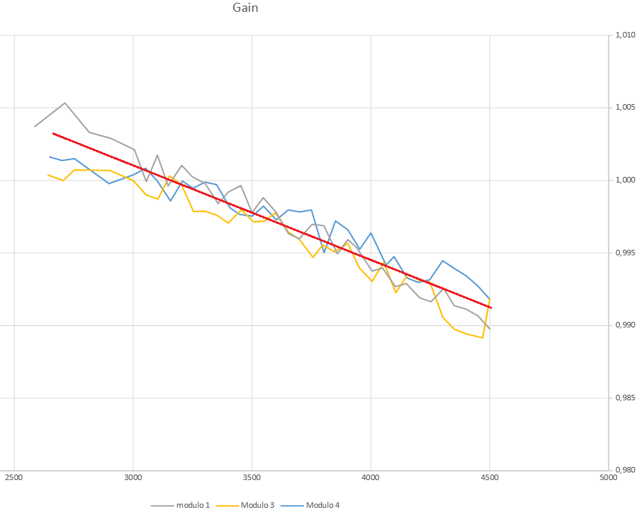
![]()
So, playing with the data, adding or subtracting an offset, I was able to superimpose the trends of the 3 gains:
![]()
So, summarizing, I found that:
- for each module, the gain varies linearly as a function of the voltage following the same angular coefficient
- In order to accurately calibrate the voltage, the user must be able to set the offset of each module…
At this point the question was: how?
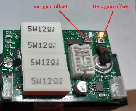
The simplest and most immediate way to perform this “one time” setting was to increase and decrease the offset using the buttons on each module, storing the Offset value on the eeprom …
![]()
The result was satisfactory !!!
I have done several tests on 16 cell modules, varying the voltage and the measurement has never shown an error greater than 10 mV!
In the following video I show how to perform this calibration:
-
Design Challenge n.3: How to program Attiny without disconnect the module from the cell
10/11/2021 at 13:06 • 0 commentsThe problem of the separation of the power supplies also arrived as regards the loading of the software in the memory of the Attiny controller.
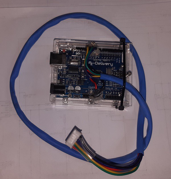
To program Attiny microcontroller I used the Arduino as isp programmer, realized by Arduino Uno board.
![]()
But how to connect the programmer (signals powered by the Arduino UNO 5v supplied by the PC USB) with the Attiny microcontroller powered by the lithium cell?
How to separate the power supplies?
![]()
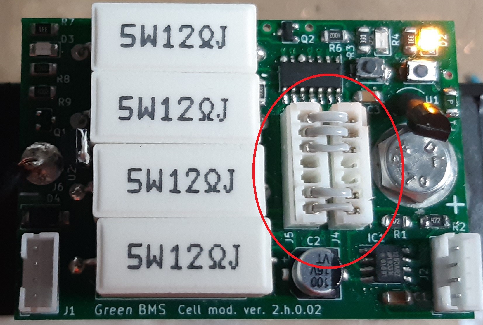
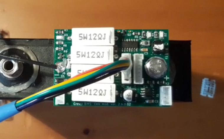
To solve this question I decided to carry out a hardware separation by means of jumpers connected to 2 connectors:
Connectors inserted = battery power supply
Connectors removed = it is possible to connect the programmer isolated from the battery
![]()
This technical solution, in addition to allowing the software upgrade without removing the module from the cell, also allows you to:
- remove power from the module (recommended during installation and removal of the module)
- perform a hardware reset of the module, avoiding the installation of the reset button
-
Design challenge n.2: what is the best way to set the cell address?
10/10/2021 at 06:51 • 0 commentsThe address of each single cell is written in a variable within the sketch of the Attiny controller:
TinyWireS.begin (address);
Obviously I couldn't create a sketch for each cell, it would have been a terrible project and impossible to manage !!!
Imagine each software release having to create n different sketches ..
So the challenge was to find a simple and user friendly way to be able to set the address of the cells, keeping a single sketch.
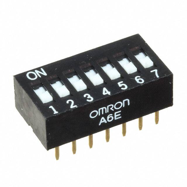
The first idea I had was to install a dip switch in each cell module.
![]()
I immediately put this solution aside, because it had a huge limit:
In order to manage a large number of cells (in perspective I would like to reach at least 72 cells) I would have had to use a 7-position dip switch.
6 bits = 64 addresses
This choice would have occupied too many I / O pins of the microcontroller!
So after some tests I found the solution I was looking for:
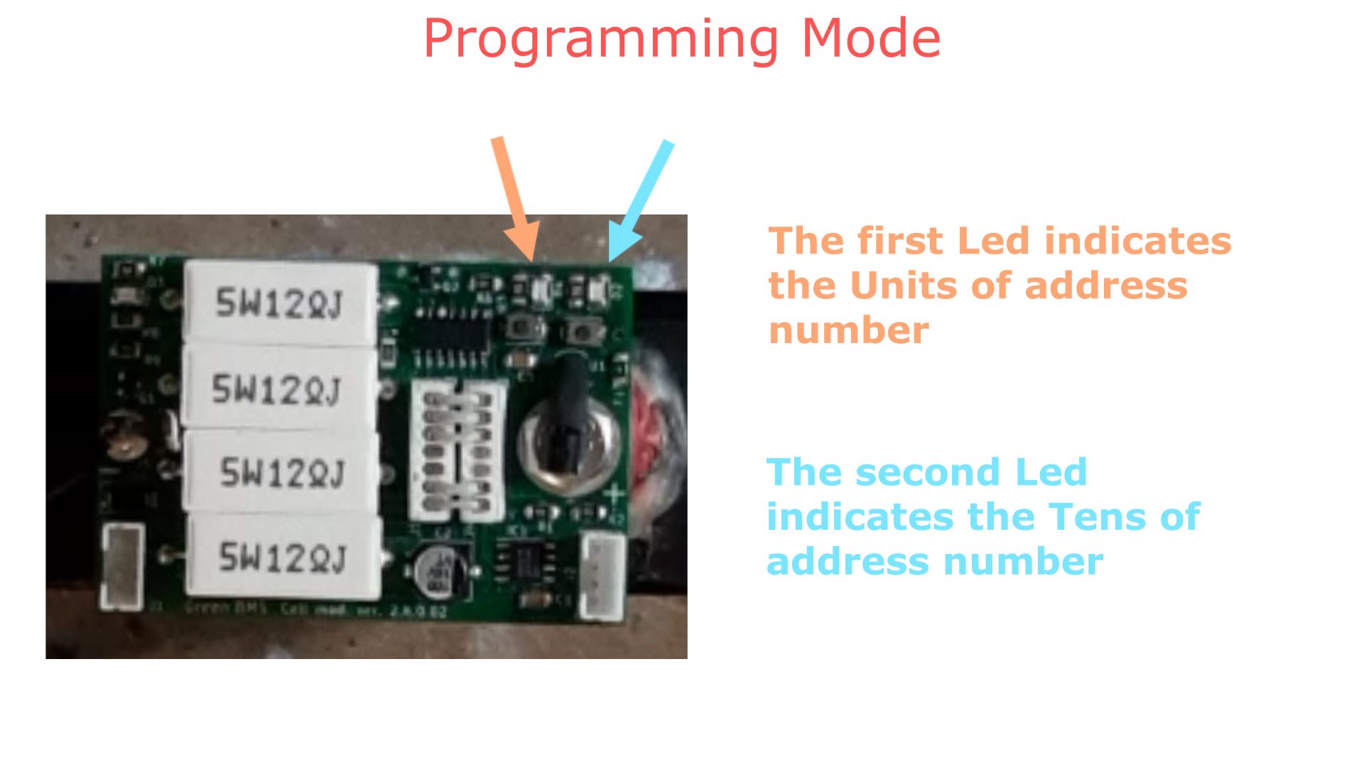
I used 2 buttons and 2 LEDs.
I have created a "programming" mode that can be activated or deactivated by pressing the 2 buttons simultaneously
![]()
I gave the user the possibility to set the cell address by setting the units (first button) and tens (second button).
The number of blinks of the LEDs is the feedback that indicates to the user how many units and how many tens.
When the user exits the programming mode, the set address is permanently saved in the Eeprom of the microcontroller.
So by occupying 4 pins, I created a solution that allows you to reach 99 addresses!
This design hurdle has also been overcome!
Here is a video that shows in practice how to set the address of each cell:
-
Design challenge n.1: system architecture and bus isolation
10/09/2021 at 10:00 • 0 commentsThe BMS I had in mind consisted of a cell module screwed directly to the poles.
To make it smart I had to use a microcontroller.
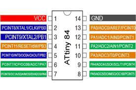
The best choice was to use an ATTiny Microcontroller ATTiny84A powered directly from the cell.
![]()
For the control unit I immediately had in mind to use the Arduino Mega board, a very popular board, with widespread online support.
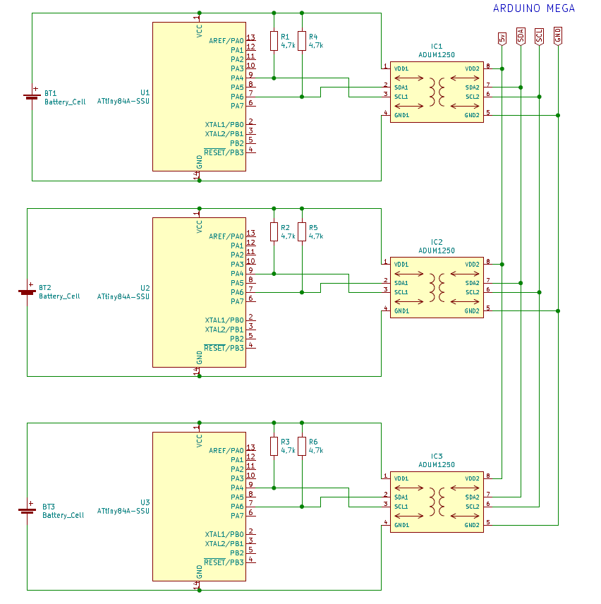
But how to manage the dialogue between Mega and the various ATTiny's?
Among the various possibilities I chose to use an I2c network, because from the programming point of view it was the simplest and safest way, thanks to the libraries available online.
But the first question was: how can I connect devices that have different power supplies (which absolutely must remain separate) communicate on the same bus?
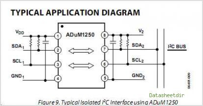
Fortunately, a suitable component came to my aid: Adum1250, a bidirectional digital isolator.
![]()
So I bought the various components, networked them together in a breadboard, addressed them and started reading and writing bytes between Arduino Mega and Attiny's.
![]()
The result was satisfactory and from this test I was able to say:
"IT CAN BE DONE !!!"
-
Balancing Check
10/03/2021 at 15:50 • 0 commentsPassive Balancing
Green BMS cell modules carry out the passive balancing. What does it mean?
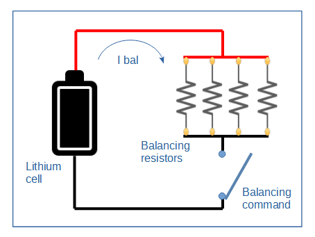
When the cell reaches the user defined balance threshold, the BMS circuit connects a power resistor of approximately 3 ohms as load to the cell, in order to discharge the cell to help the entire battery pack balancing.![]()
In many BMS systems, the verification of the correct functioning of the balancing circuit is difficult to carry out, because it is necessary to create the unbalanced conditions of the cells, moreover in many cases it is impossible to test the balancing circuit of all the cells.
For this reason, when designing Green BMS, I wanted to add a test function that I think is important: the balancing check.
Balancing Check
![]()
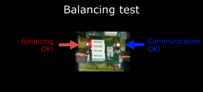
The operation is very simple: you have to connect to your battery pack using the Green BMS App and press the button relating to the cell whose balancing circuit you want to test.
![]()
At the same time you must check the status of the LEDs on the cell module and make sure that the “Balancing OK” LED lights up and the “Communication LEDs” alternate fast and intermittently.
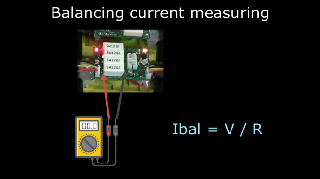
During balancing test you can also check the real balancing current measuring the voltage drop across the resistors and applying the Ohm’s law formula Ibal = V / R (R=3ohm).
![]()
How to perform balancing check video tutorialIn the following video I show you how to perform this test.
bye bye -
Where to buy
10/03/2021 at 15:37 • 0 commentsGreen BMS is an open source project, so you can download the gerber files from download page and you can buy the cards wherever you want.
Alternatively you can purchase Green BMS components on PCBway Store.
For each component there is the possibility to buy only the PCB by carrying out the do-it-yourself assembly, or ask PCBway for a quote to receive the board already assembled, using the BOM file included in the product page.
If you are not yet subscribed to PCBway, you can do it at my invitation link: https://www.pcbway.com/setinvite.aspx?inviteid=436793
These are the pages where you can buy the PCB's:
 Sergio Ghirardelli