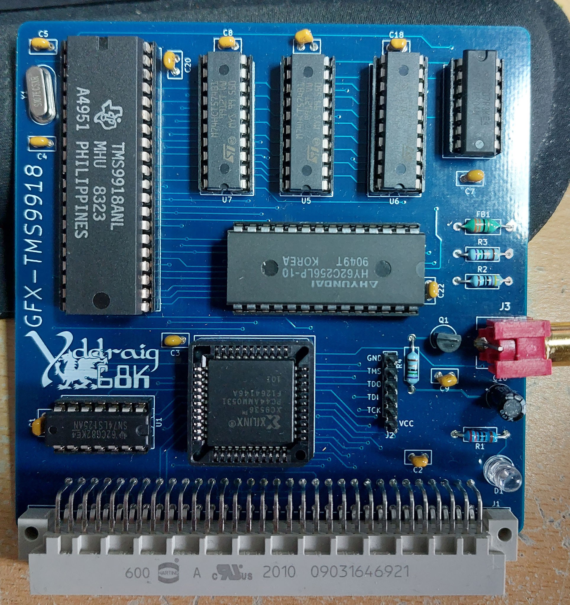
When I ordered the new PCB for Y Ddraig, I also ordered some additional expansion card PCBs. A couple of these I had made previously and just moved the design from Proteus to KiCAD and making a few changes to the design. Others were new boards and will be interesting to get up and running.
The boards are a mix of graphics, sound and peripheral devices. There's 3 graphics boards based on the TMS9918A, V9958 and the V9990 chips. Two sound boards based on the YM2151 and the YM2612 and some periperals boards for a floppy disk controller using the WD37C65C, Ethernet using the RTL8019AS and a joystick interface for Sega Megadrive (Genesis for the US) controllers.
One of the reasons I changed Y Ddraig from a single board computer to using expansion slots was to be able to experiment with some of these old chips and this is the first of many that I'm testing.
The first board I chose to start with was the TMS9918 video controller. While it's lacking in capability compared to some newer solutions, I wanted to try something with this chip as it was used in the Colecovision which I had a kid, a console that my brother and I spent many hours playing as kids. It was also used in
I chose to use the TMS9918A for this rather the TMS9929A PAL version as it directly outputs composite directly, and most TVs can handle NTSC these days.
The TMS9918A is capable of a 256x192 pixel display with a 15 colour palette. It has 16K of video memory and 4 different video modes.
From the Sega Retro site:
There are 4 different screen modes available in the TMS9918A (as mentioned before, the TMS9918 lacks mode Graphic II):
Mode 0 (Text): 40×24 characters monochrome. As the display is 256 pixels width, the character set is only 6 pixels wide. This mode doesn't support sprites, nor a separate border color setting.
Mode 1 (Graphic 1): 32×24 characters (256×192 bitmap), where for each 8 characters in the character set the foreground and background color can be set. The chars "0"-"7" for example all have the same attributes.
Mode 2 (Graphic 2): 32×24 characters (256×192 bitmap), with a 2-color limitation for each 8 pixel wide line inside a character.
Mode 3 (Multicolor): 64×48 mode, very blocky and rarely used. Each 'pixel' can have its own color defined though, hence the name. Its sprites still have the same resolution as in screen modes 1 and 2.
The TMS9918 has a fixed 16-color palette (actually 15 colors + transparent).
The TMS9918A was designed to use DRAM, but I have used the design by Leonardo Miliani that allows SRAM to be used instead.
Bring up the board went well in some ways but initially I had nothing on the composite output. Mistake on the footprint for the connector meant that the signal and ground were swapped. I made up a simple cable that swapped the signals and i managed to get a signal on the monitor.
I wrote a couple of simple test program just to make sure that the board was working correctly. One to write something to the screen in text mode and a simple test of the graphics mode.
It would be nice to get something better running on the board before I move on to the next one but at this point I can call it a success.


 Stephen Moody
Discussions
Become a Hackaday.io Member
Create an account to leave a comment. Already have an account? Log In.