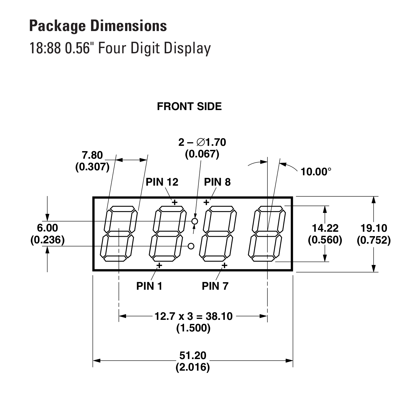
The seeds of this project started when I scored 500 "18:88" common-cathode new-old-stock LED displays on eBay. I think these were intended for clocks (that can't do 24-hour mode, boo). There doesn't seem to be much demand for these displays, so I got them for a song or two, plus shipping.
They came in two fairly large, heavy boxes, which provided impetus for me to convert these boxes into something fancy I could hang on the wall instead of taking up storage space.
Each of these HPDS-B05G displays is a through-hole component with four digits and a colon. The digits are each broken out to their own cathode pin. The segments in all four digits are connected together, so a given position is the same anode pin among all four digits. (The colon gets slightly different treatment, as it becomes a "DP" pin associated with digits 2 and 3, and the first digit only has two of the eight segments.) You're intended to scan through the displays: set all of the segments to a given digit's values, begin draining current through its cathode pin, and cycle through all four digits this way. Do this quickly enough and it appears seamless to our eyes.
You can do this with most microcontrollers, which is perfectly nice and makes it easy enough, given enough pins, to get some nice blink goodness going. But I have done a few other projects with the ISSI IS31FL3733, which is a 12x16 LED current-controlled matrix driver that takes care of 8-bit PWM, overall brightness range, short detection, and other goodies. Having greyscale control of each of the segments is actually quite a lot of fun! So I decided to use this chip for my display panels in this project. I can just give it greyscale values and it makes the magic happen!
The 12x16 (cathodes * anodes) arrangement of the chip aligns fairly well with the 4x8 arrangement of the matrices, letting me pack six displays into a neat panel, using 150 / 192 possible segments. I wired up two parallel "chains" of the HDSP-B05Gs, using CS0:7 for one chain's segments, and CS8:15 for the other. Then I wired together the anodes the other way, using SW0:3, SW4:7, SW8:11. This gives me 150 segments per panel (25 per 4-digit 18:88 panel, with independent colon dots and no decimal points.) If I'd had 8.8.8.8. or 88:88 panels, could've had more segments for "free."
I cranked away on a Very Exciting Spreadsheet for a while. I wanted to have a display of a common aspect ratio, such as 4:3, 3:2, or 16:9, to make mastering the content easier. Measuring the aspect ratio of the physical devices and adding padding and such let me figure out the real size of the panels. With each panel packing 2-wide, 3-high of the 4-digit displays, it turned out to work well to have 6 panels wide, 8 panels tall, for a total digit dimension of 48x24 digits; believe it or not, this ends up being 4:3, with the heights of the digits taken into effect.
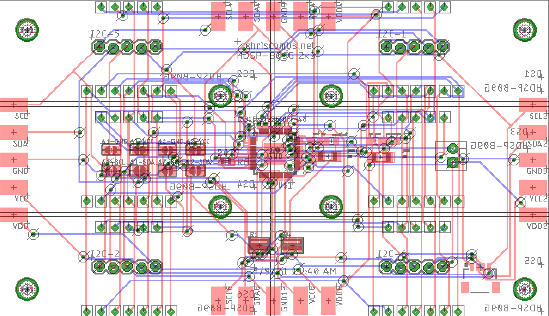
I laid out some boards in Eagle, following in the footsteps of some similar boards done previously. This time I made sure to include lots of extra connectivity options--I used "Qwiic," JST-XH x 4, and some panel-edge connectors that can be cross-soldered across multiple boards. The JST-XH connectors ended up carrying the day here.

(Yes, autorouted.)
This chip communicates over the I2C bus and can have one of 16 different addresses. "But there are 48 controllers!" I hear you thinking. Stay tuned for my next project post, about the joys of using multiple I2C buses on the Raspberry Pi 4 with new kernel hooks provided by device tree overlays.
 Chris Combs
Discussions
Become a Hackaday.io Member
Create an account to leave a comment. Already have an account? Log In.
Wow, this is an impressive project, looking forward to elaboration. I see there are still some listings for bulk buys of that model display on eBay. Fortunately shipping to here rules it out so I can resist the temptation.
Are you sure? yes | no