 agp.cooper
Low Signal Strength?
I assembled the two transistor reflex circuit:
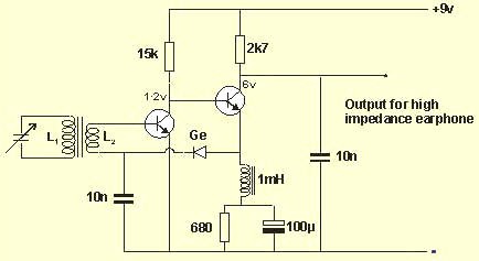
I went with this design as I have built it before and it works.
I did model this circuit in the simulator and the Ge diode can be swapped with a silicon (the diode bias current is about 1.8 uA).
Also the audio output increases as a square of the signal strength (interesting?).
Well the performance was poor, I could just make out a local 720 kHz station.
- Had to ground the tuning coil to the circuit ground to stop audio oscillation.
- Plenty of hum from my soldering iron.
- Plenty of transistor noise.
- All the transistor voltages are correct.
- Not much better than a crystal set with a good antenna?
- Swapped my coil with a MW ferrite antenna coil and it was worse?
So I think the circuit is working properly, just low signal?
- Swapped out the Ge diode (1N34A) for a 1N4148 and the performance is about the same (maybe better).
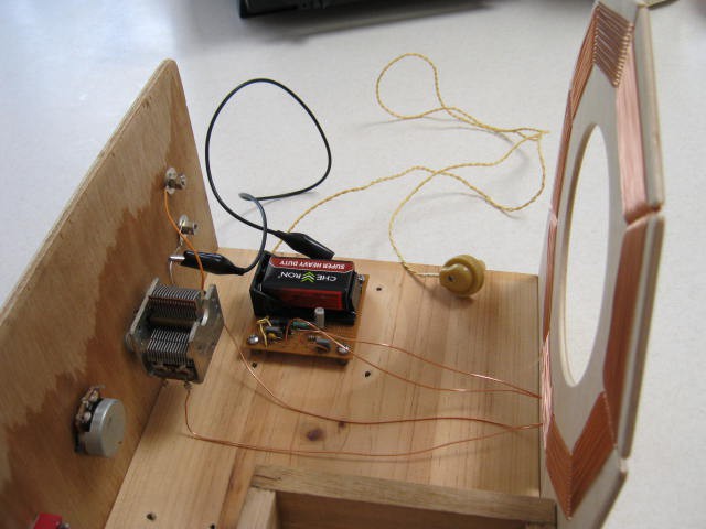
Here is the reflex:
And here is the DIYLC design:
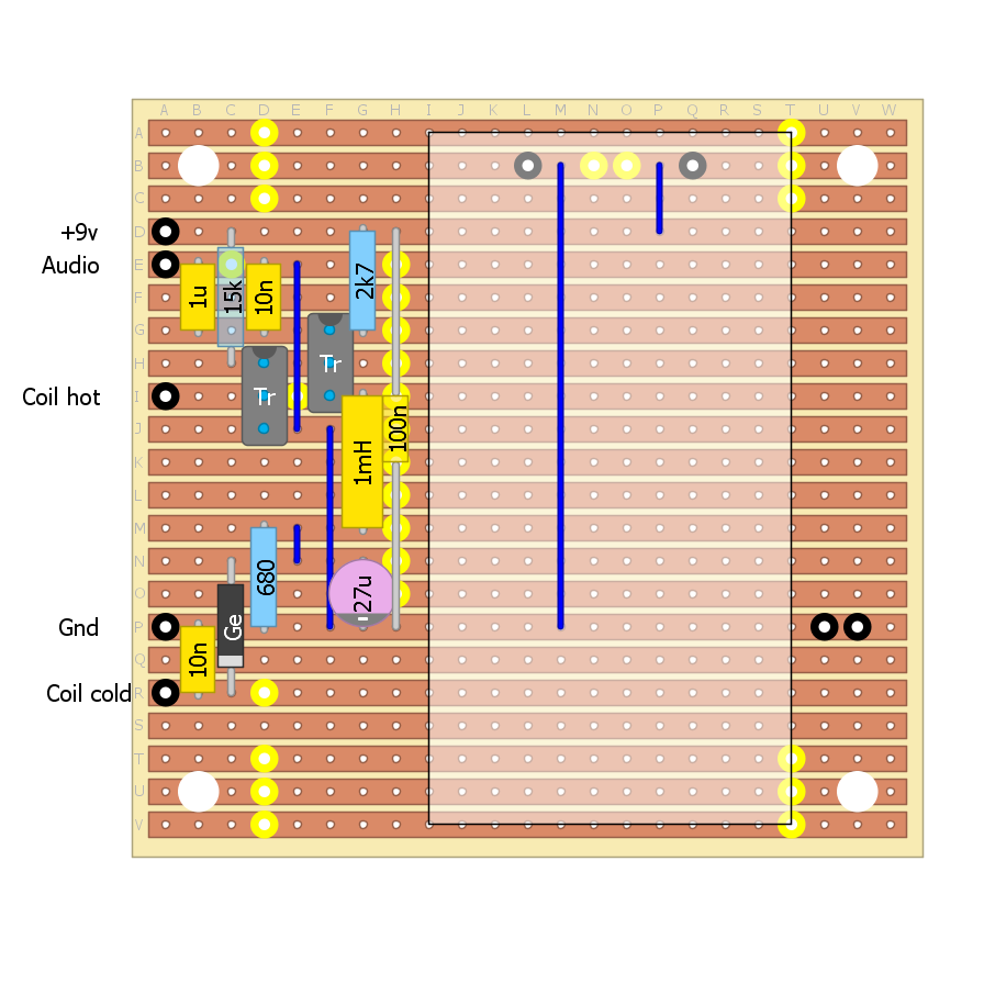
Th only change was to reduce the 100 uF emitter by pass to to 27 uF (25 uF would have been better) to centre the audio gain at 1 kHz.
AlanX
Discussions
Become a Hackaday.io Member
Create an account to leave a comment. Already have an account? Log In.