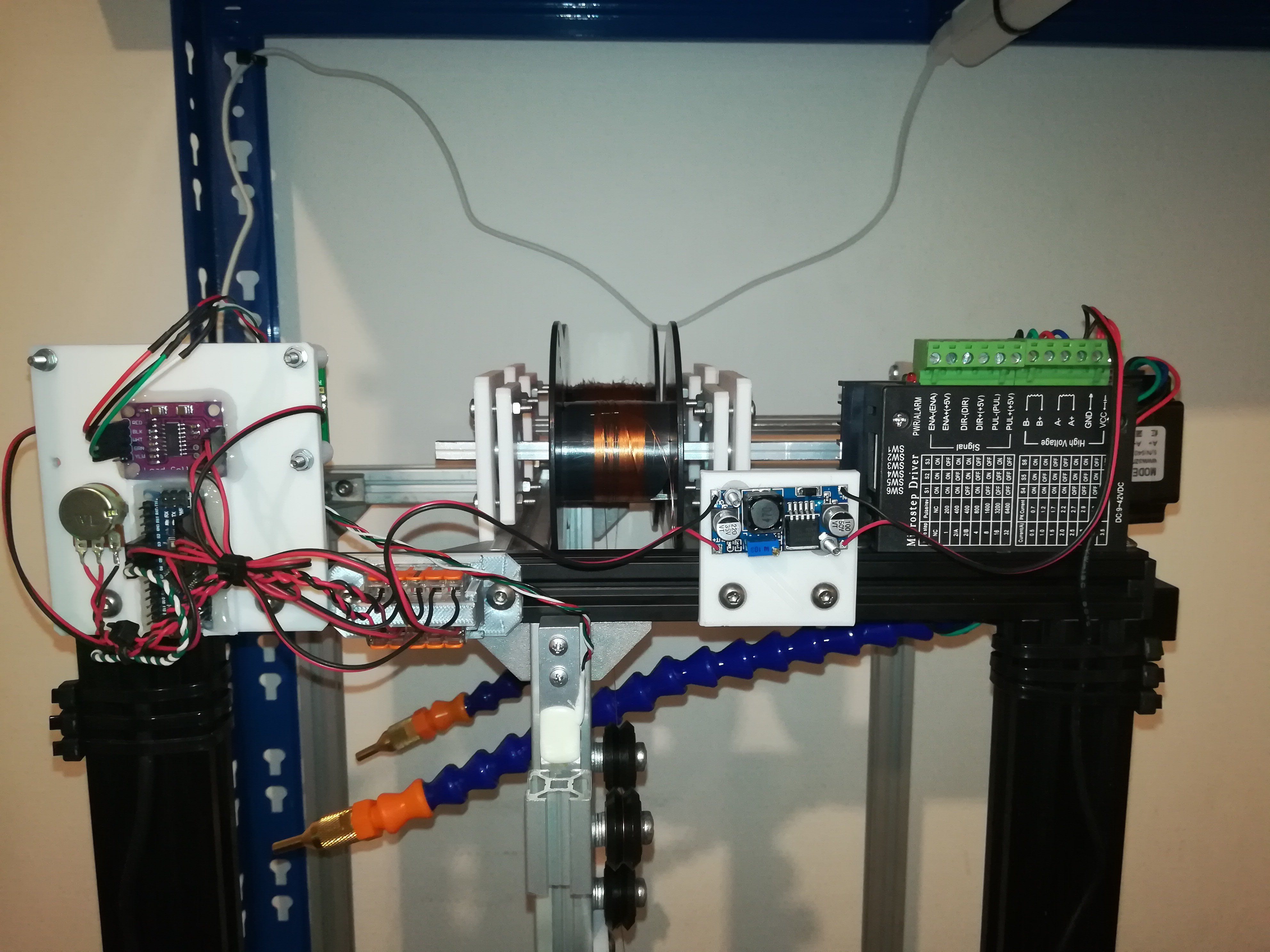
Here are some pictures of my latest progress, where you can see the spools, load cell, encoder and guide rollers.
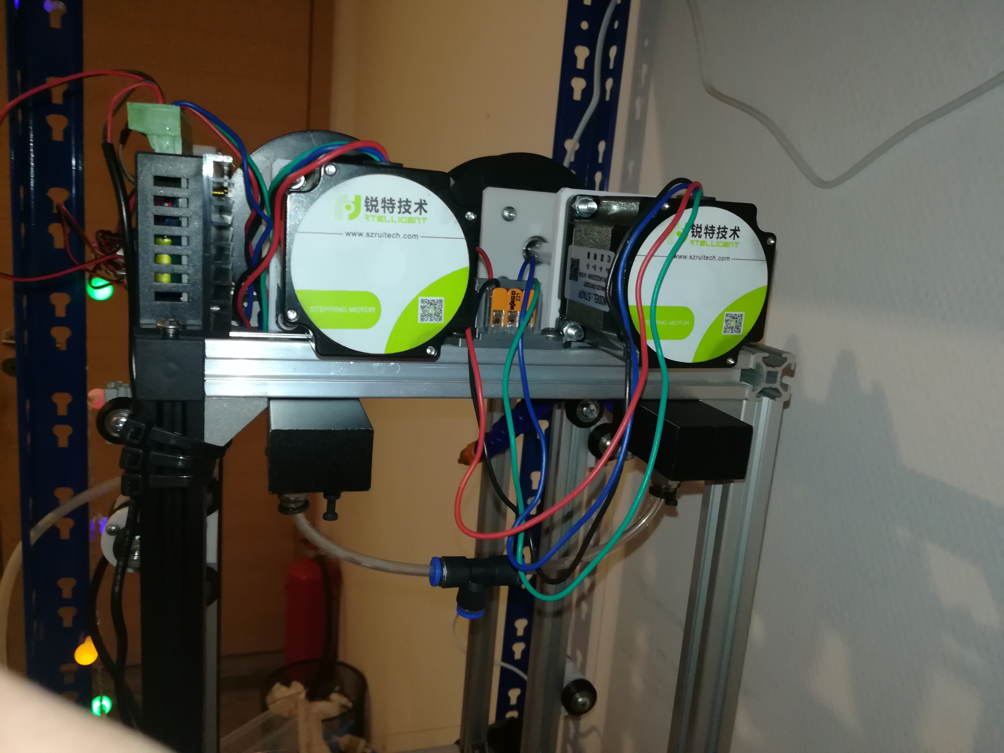
I used two welding wire spools and grooved 625ZZ (Ender 3 Rollers) for guiding the wire, Nema 23 motors for driving the wire and mounted it in a horizontal setup, so that the wire can stay on its position while the workpiece can be moved along the X and Z axis. I thought this could maybe made the machine easier to build, because you only have to add some rollers and parts to the frame to build the wire guide.
Now I'm working on the electronics for driving the wire, so that I can do a test run as soon as possible.
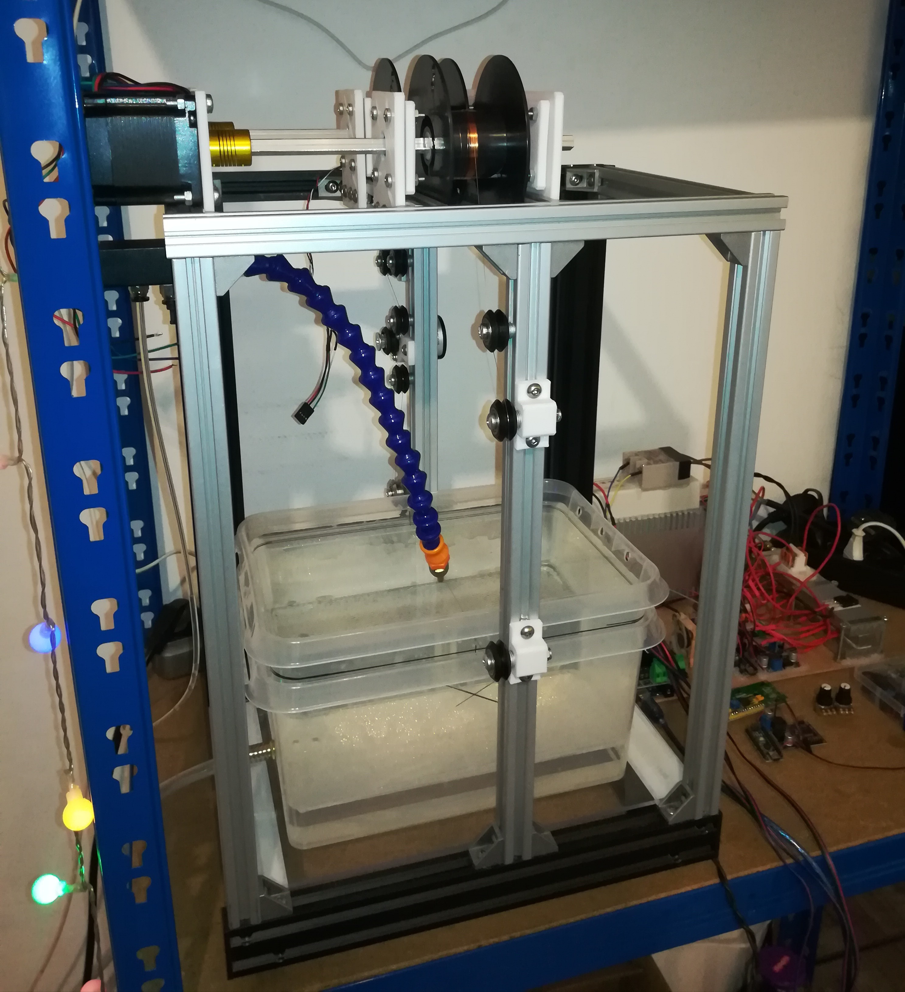
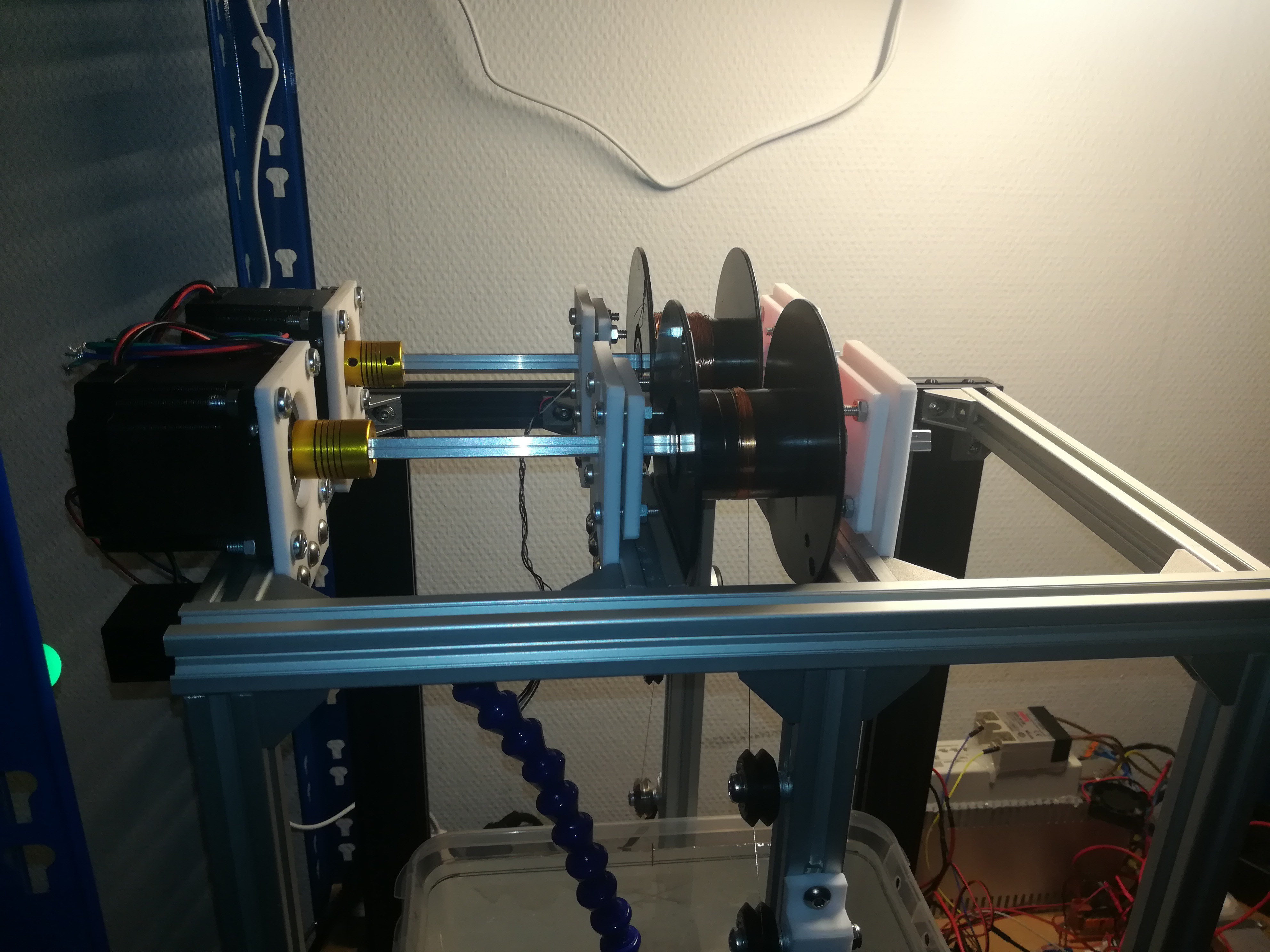
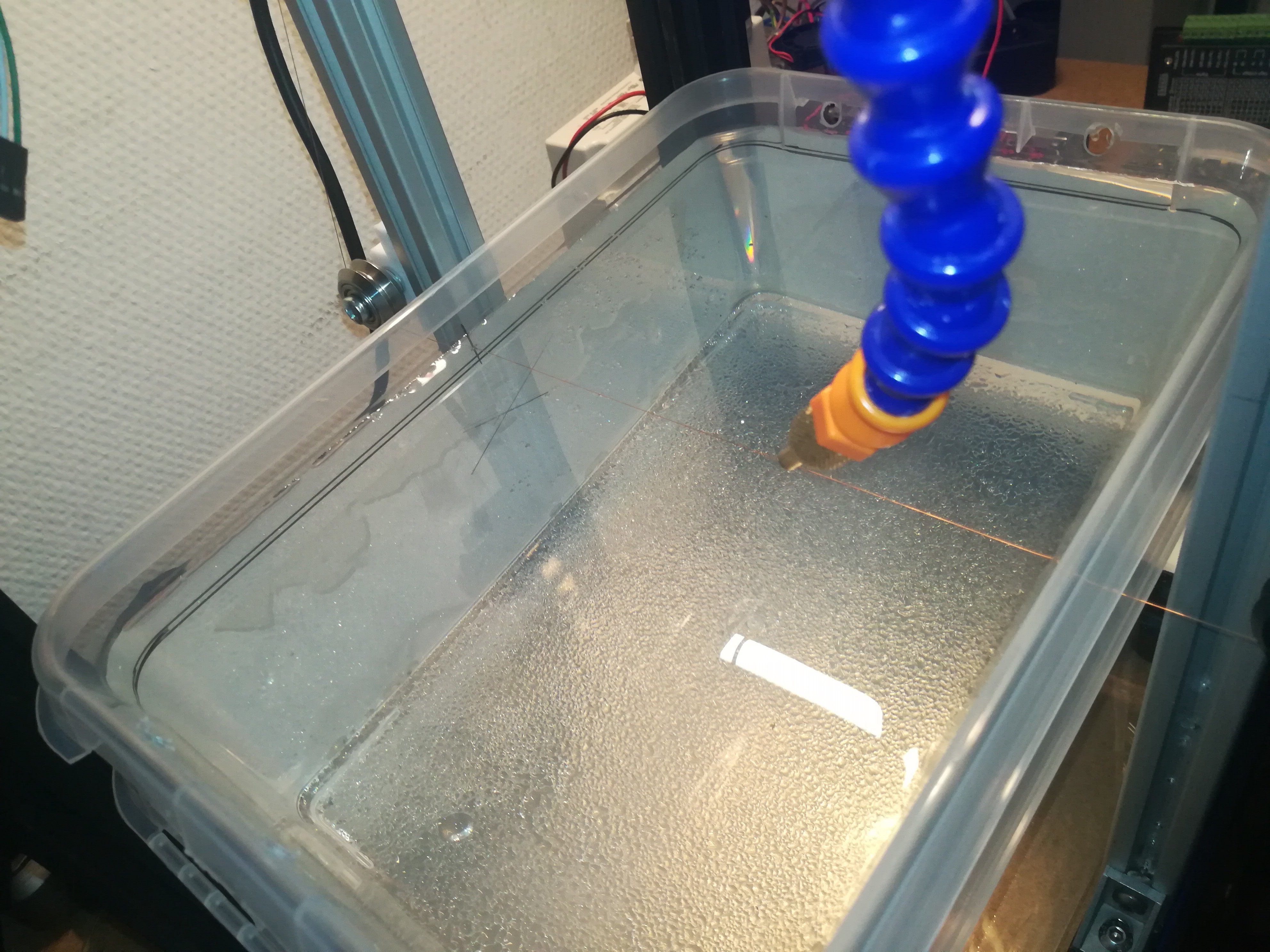
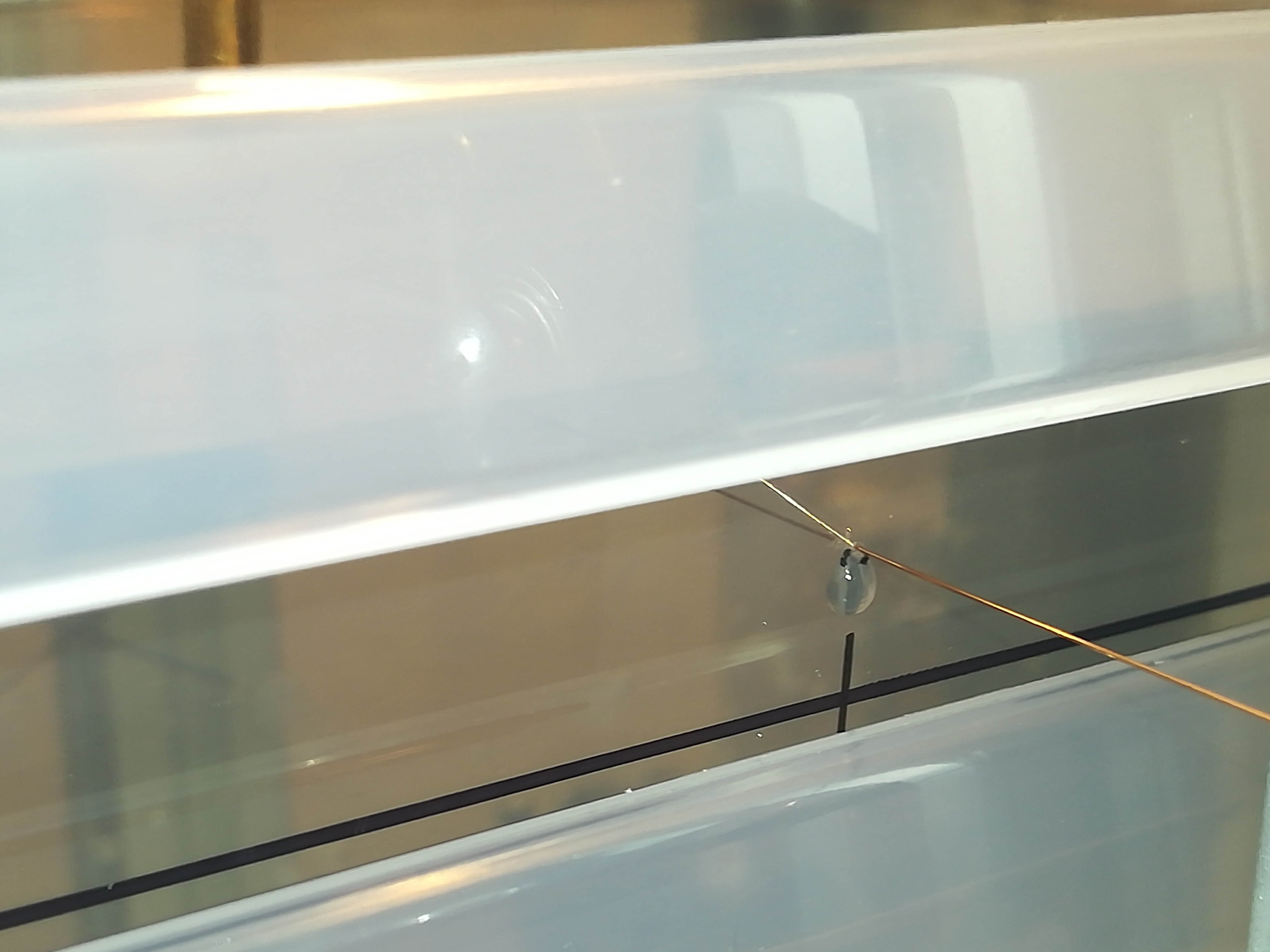

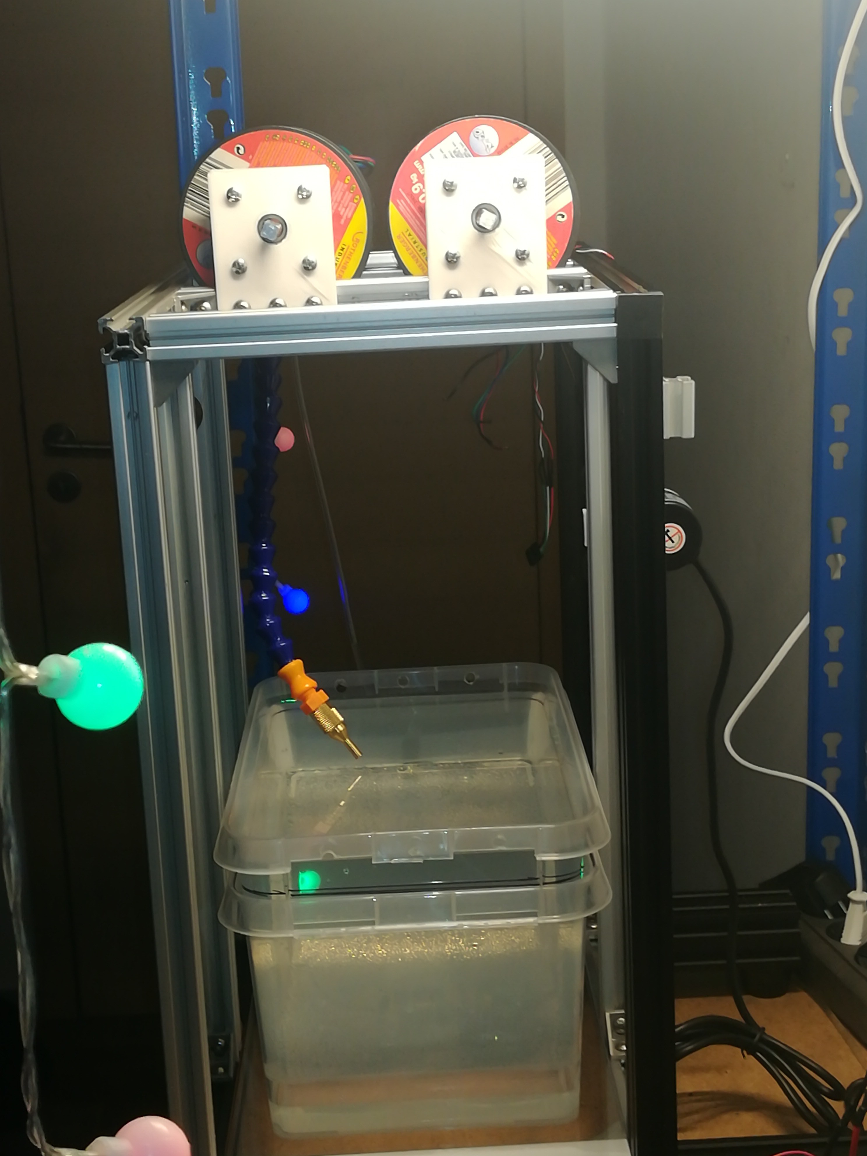
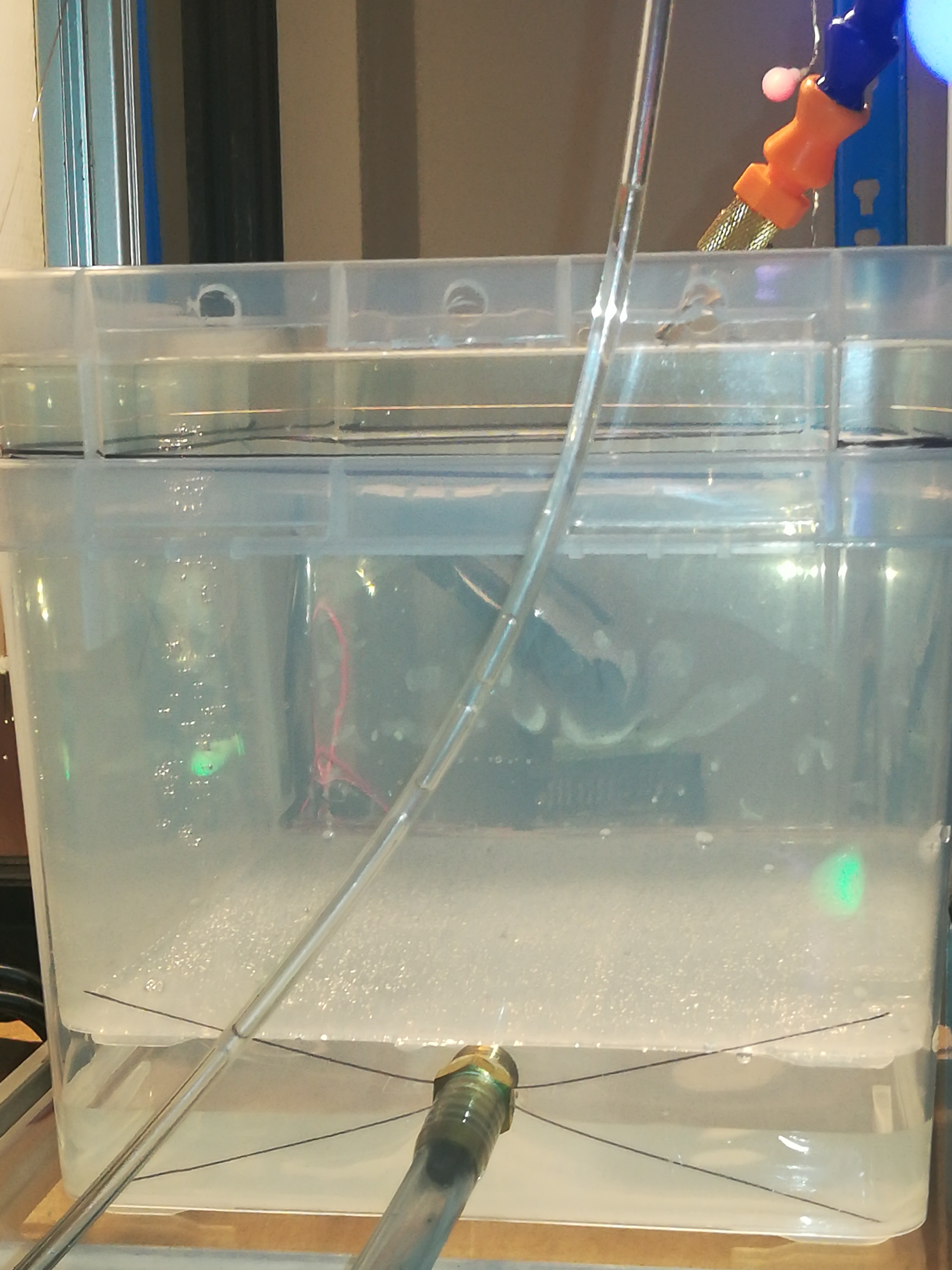
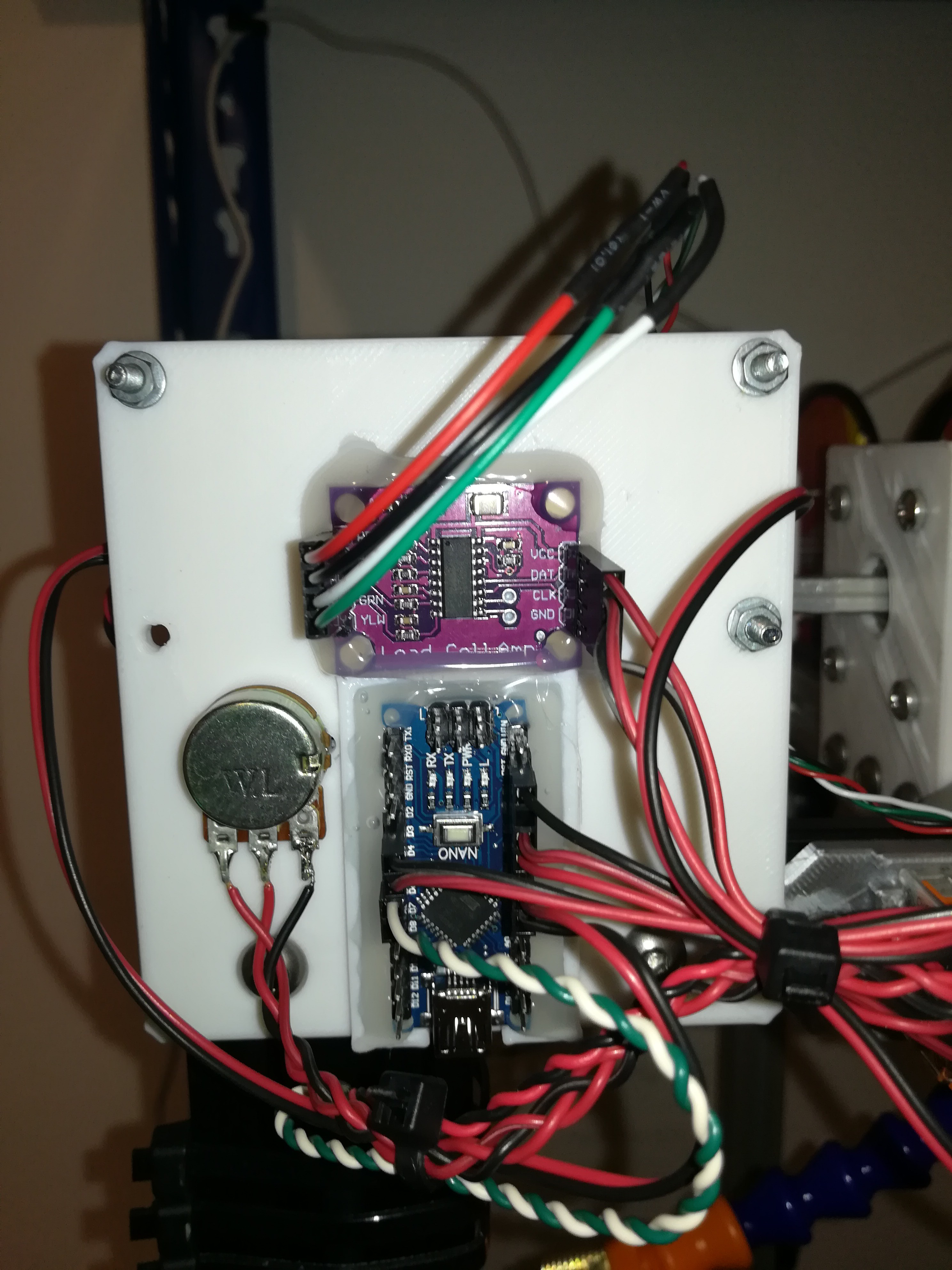
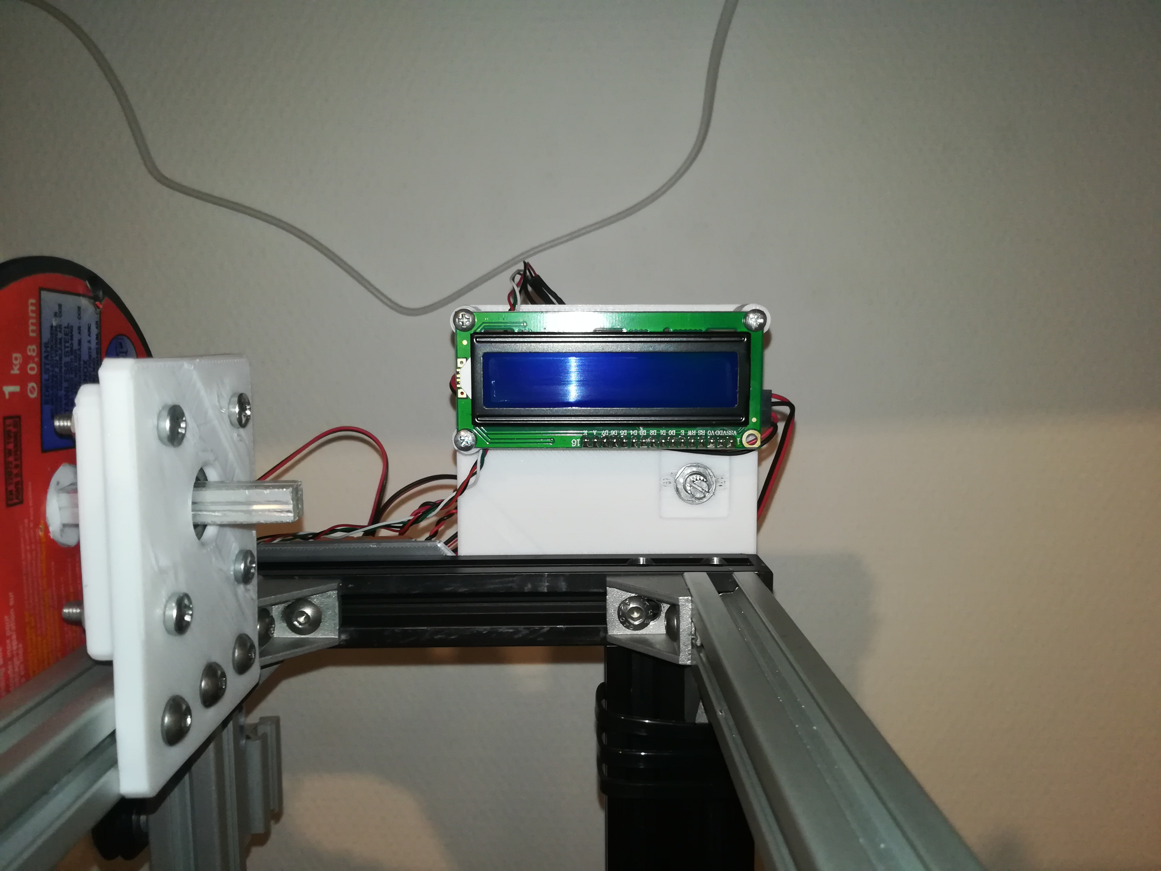
I added and connected some electronic parts. This is one possible solution for driving the wire. I shorted both windings of one stepper motor to provide some resistance for tightening the wire and connected the other stepper motor to a driver for pulling the wire and also connected an encoder, load cell, I2C LCD and potentiometer to an Arduino NANO. The encoder is used for measuring wire speed and the load cell is used for measuring the tension of the wire. If the wire would get wrapped around the spool at constant speed, the outer diameter would increase and with it the wire speed. Instead of that I want to measure the wire speed with an encoder and adjust the speed of the stepper motor to keep the wire speed constant. For now I only want to use the measured tension for monitoring and testing. Later, both values, wire speed and tension should be displayed on the LCD and the potentiometer should be used for adjusting wire speed.
With everything wired up it's time to write some Arduino code to get ready for testing.
 Dominik Meffert
Discussions
Become a Hackaday.io Member
Create an account to leave a comment. Already have an account? Log In.