 Justin Skists
Overall
In this project, I am not going for full Jupiter ACE compatibility. I'd like to work toward it, but there is no way I'l be able to complete it by the end of October. My challenge is to run the official ROM, not every single demo! :)
My initial thoughts are to take a standard RC2014 with the following items, and add my new "challenge" modules:
- Enhanced backplane
- Z80 Module
- Dual clock module (currently at 7.3MHz, with option to support external clock for the Jupiter ACE frequency)
- Pageable ROM module (flashed with Jupiter ACE ROM image)
- Pageable RAM module
The Interface Module
The Jupiter ACE had very simple I/O. Basically, everything on-board was accessed by a single Z80 I/O port: 0xFE. (To be honest, looking at the schematics, it's actually accessable by every odd-numbered port address! But, officially, it's 0xFE)
This port gave access to:
- the keyboard
- the speaker
- the EAR socket (for tape loading)
- the MIC socket (for tape saving)
This is what I'm thinking of:
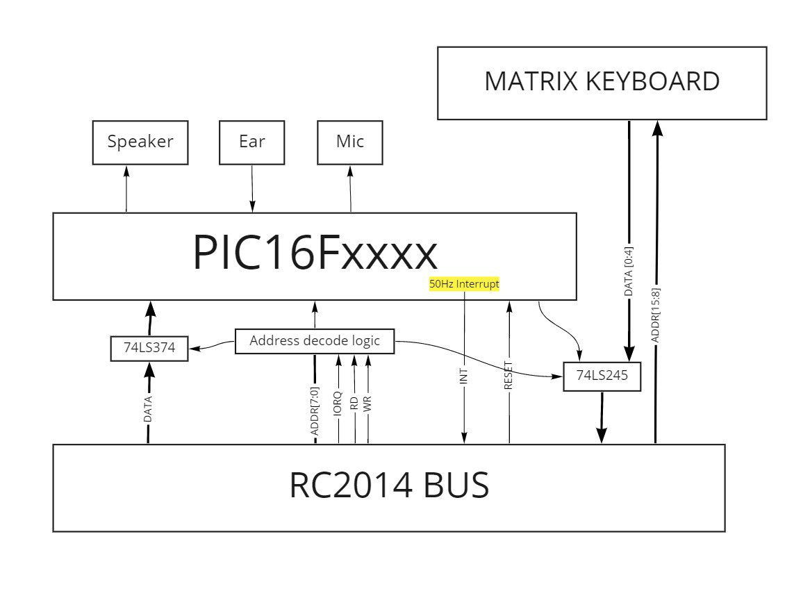
I originally choose the PIC18F4520, as it has the "parallel slave port", for microprocessor interfacing. Handy!
However, I didn't beleive the microcontroller could read the "keyboard", to place the value into the port, quick enough before the Z80 finished its read-cycle. So, I would need to choose another microcontroller; probably PIC16F1509 or PIC18F26K22 (as I know that I have at least one of them lying around), and use a couple of 74LS' chips to implement the read and write port.
I'll probably not get tape saving/loading completed in this challenge, but I'm leaving it open for future development. The reason for using the PIC, is that it should be possible to process the tape audio and save it to EEPROM, output hex-file through a UART, or similar. Also, the PIC will provide the 50Hz frame interrupt.
Video module
The Jupiter ACE has a nice memory-mapped character-based monochrome video. It was implemented using TTL logic!
There is no way I'm going to be able to replicate it in the time given.
So, I'll be taking my inspiration from the BusRaider module. In this case, a PIC microcontroller will read the area of RAM, that hold the the Jupiter ACE's screen and character map, which will then be passed to the Raspberry PI (via SPI) to decode and display to screen.
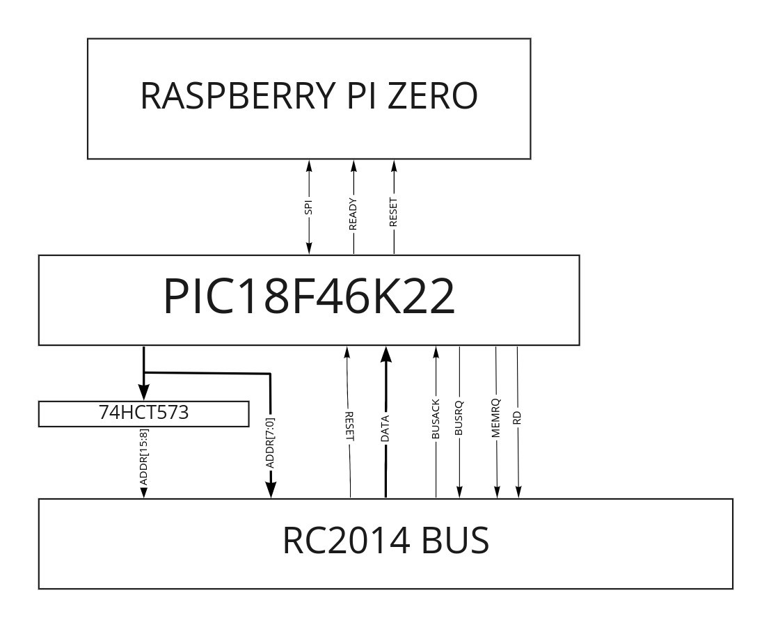
My choice of the PIC18F46K22 is because it is a 40pin IC, plenty of pins to access the Z80 bus, and has enough RAM to read and store the area of memory read for Jupiter ACE, before passing it to the Raspberry PI.
Yes, using the Raspberry PI as a vdeo card is cheating, but there is precedent for its use in the RC2014 world. I'm not a hardware engineer, and I don't have the tools to create and debug a full-on TTL VGA/HDMI video interface, so I intend to push that problem into a domain I'm much more familiar with: software.
I'm fully aware that I won't get 50Hz frame rate using this setup. I'm just hoping for enough frames-per-second (FPS) to make it usable -- to be honest, I'd probably be happy with just 1 FPS, as long as I can see something!
Discussions
Become a Hackaday.io Member
Create an account to leave a comment. Already have an account? Log In.