 Michael Gardi
My Fubata MD-4PCS key switches finally arrived! Time to get the keyboard put together. The first step was to add the 85 IN4148 diodes. To save some time I printed a diode lead bender from Thingiverse.
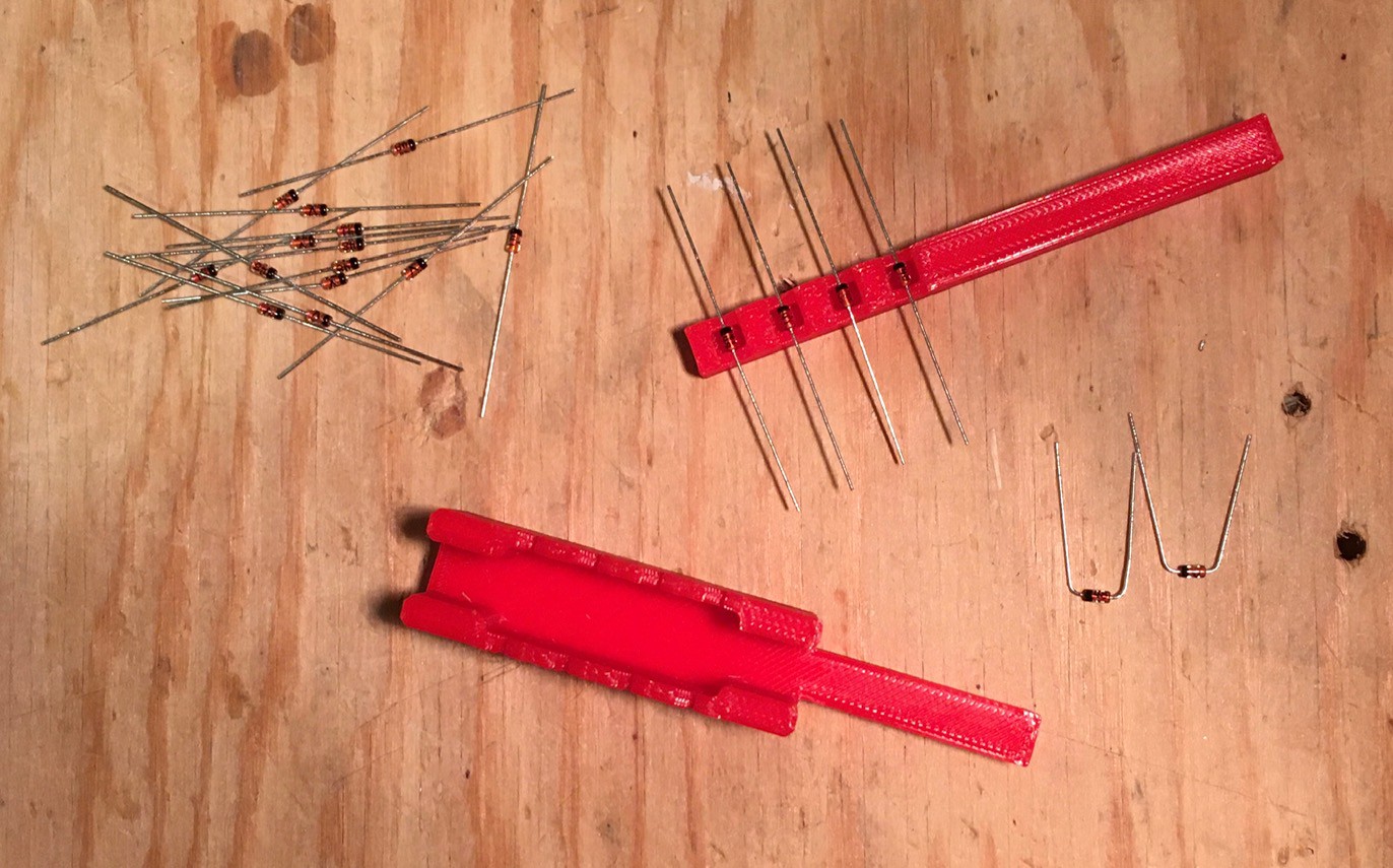
I was super careful to double and triple check the orientation of each diode since trying to replace one after all the switches are installed would be very hard.
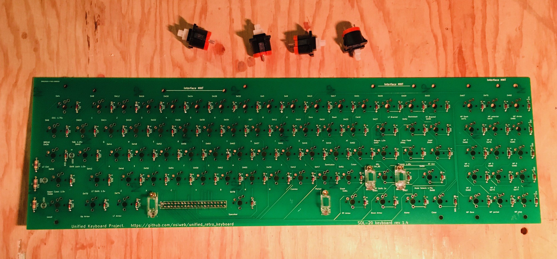
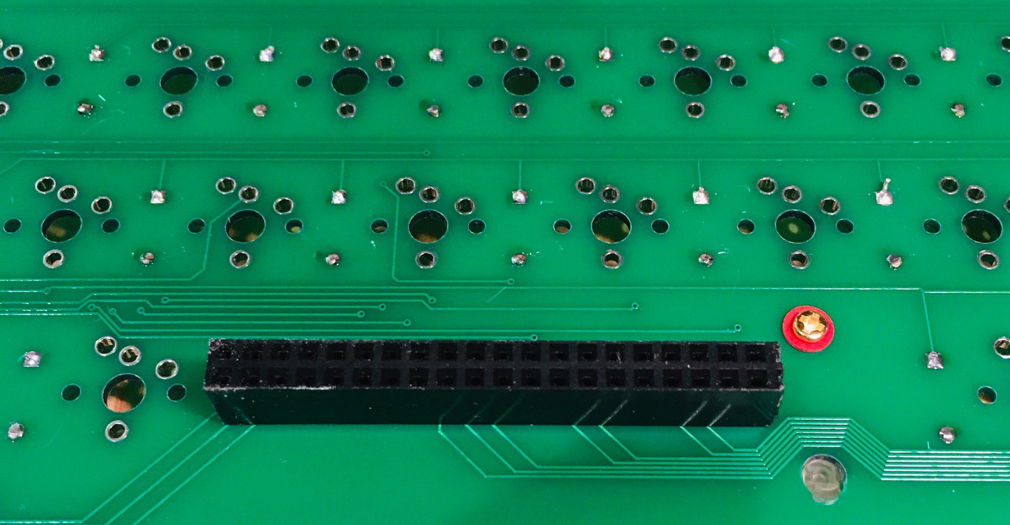
You can also see that I have installed the screw-in stabilizers for the space bar and Shift keys plus the three limiting resistors for the Local, Upper Case, and Shift Lock key LEDs. On the back a 2x20 pin female connector was added to mate with the encoder.
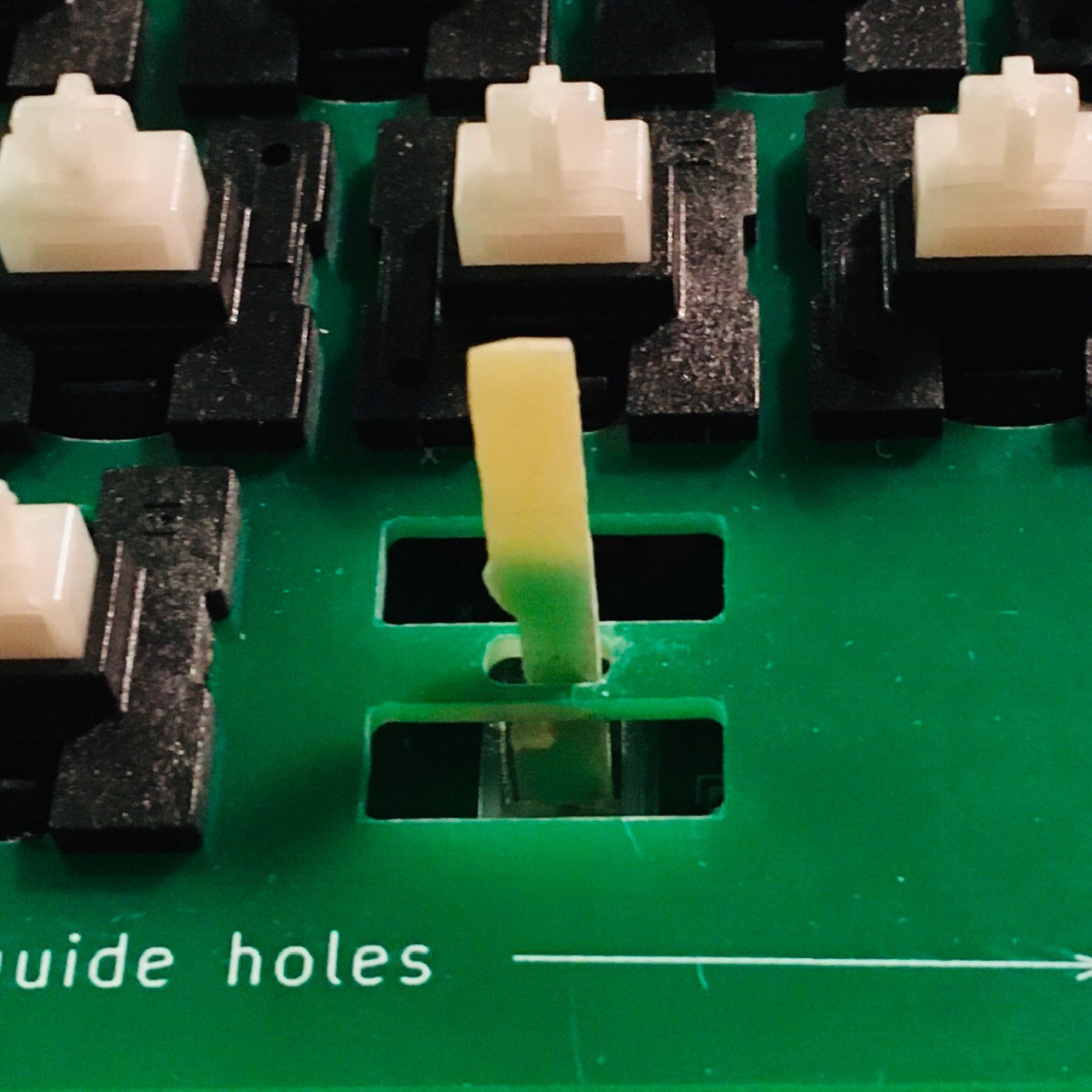
On the aligner PCB there are four extenders to be used with the Spacebar and Shift Stabilizers.
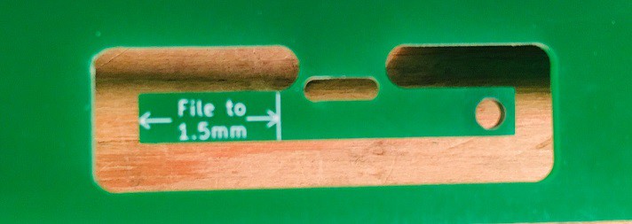
Snip these off and as the text instructs you have to file down one end so that it is 1.5 mm thick so they will fit into the keycaps.
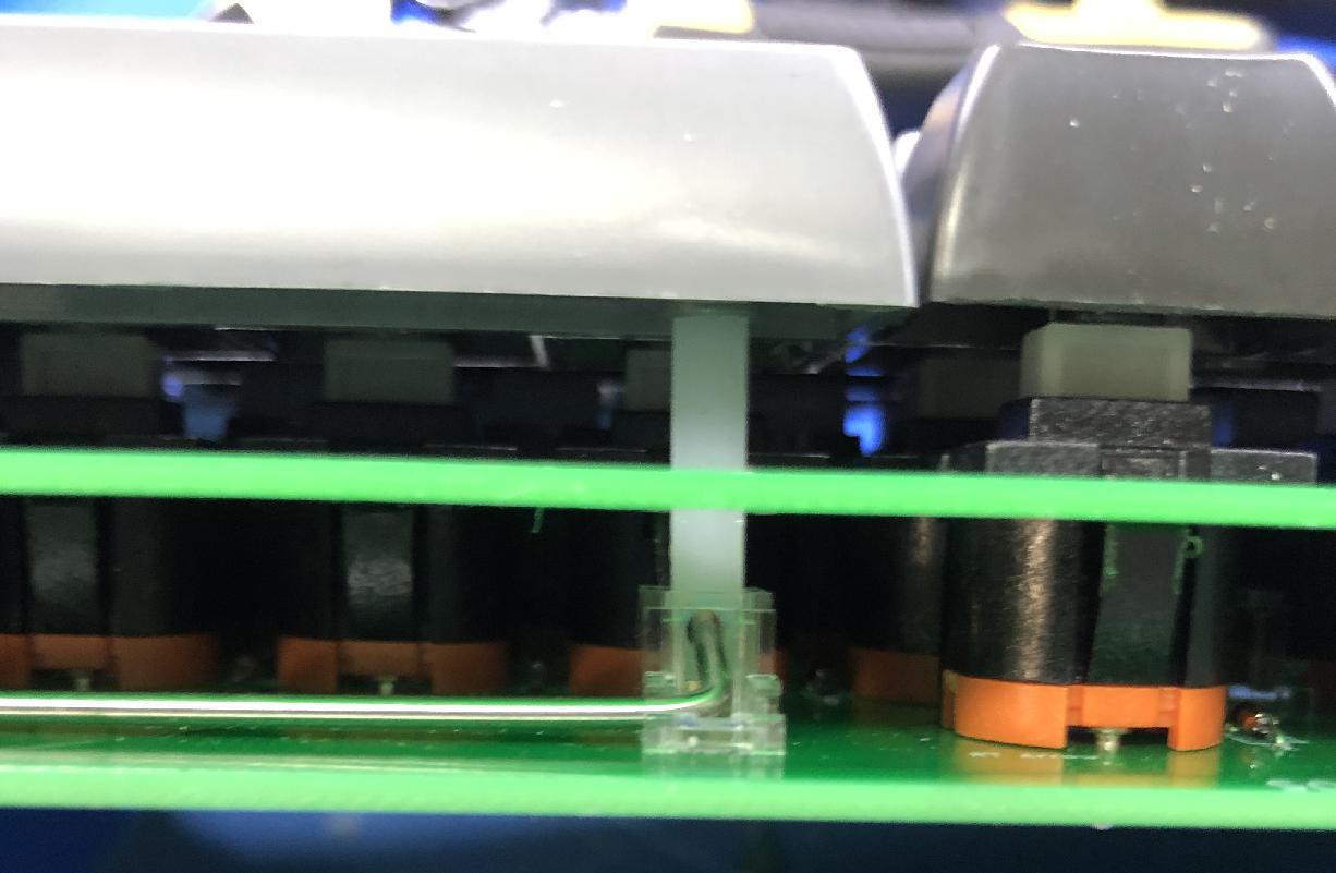
This is how they will be installed when you first start adding switches attaching the aligner and keyboard PCBS.
Make sure that they pass through the openings in the aligner as pictured above.
I followed Dave's advice adding the switches.
- Snap a few Futaba keys into the aligner, perhaps 3 or 4 evenly spaced per main keyboard row, and one at each corner of the keypad. Then fit the aligner with keys to the keyboard PCB. At this point you should have the extenders connected and ready to go as pictured above.
- Solder in one lead of each switch. Then, go through all the switches and reflow each solder joint while applying tight clamping pressure (with your fingers) to push the aligner and PCB together so each switch is flush. This makes a torsion-box structure for the keyboard.
- Now solder the second lead of each switch.
- Now snap in a few more keys, spaced evenly between the already installed switches, and repeat the same procedure as above.
- Now install the rest of the switches, snapping in enough switches to fill one of the gaps between keys, then soldering all the leads at once.
![]()

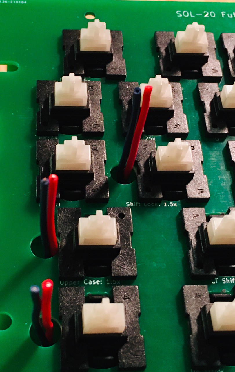
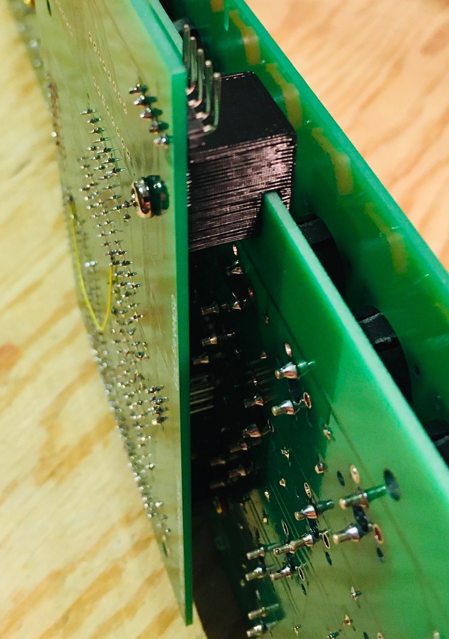
Here is what I have so far. The wires you can see on the left had side of the keyboard are for the Local, Upper Case, and Shift Lock key LEDs since I found that the leads on the LEDs that I had were too short.
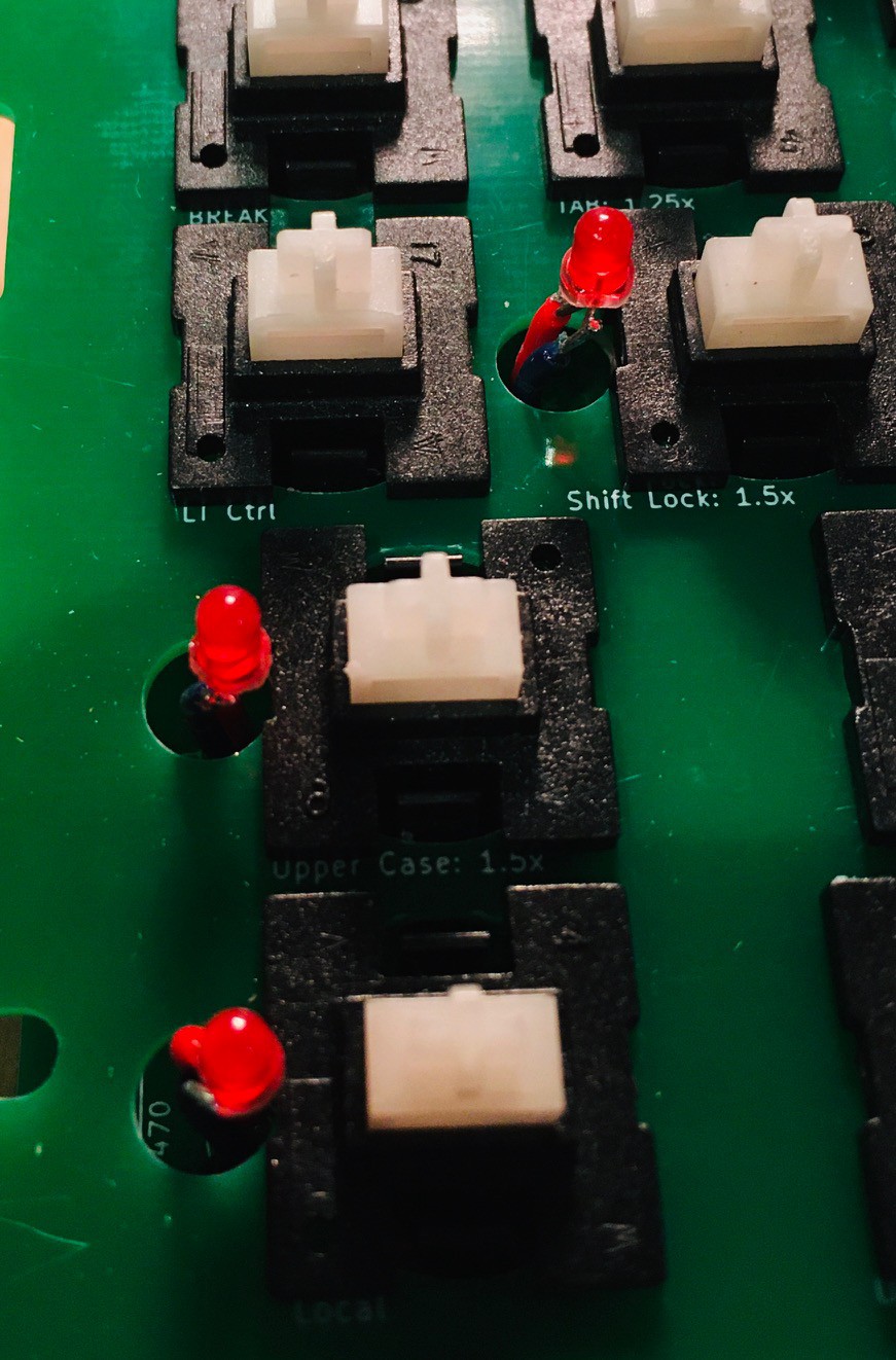
Using one of the keycaps I cut the wires so that when the LED was attached it would extend up into the keycap without touching the top when the key was depressed. Looks like this.
Finally I attached the encoder via the 40 pin connector. There were holes on the encoder and keyboard PCBs but I found they did not line up correctly and would have been hard to reach at any rate. So I printed a brace to secure the front part of the encoder board.
That's pretty much it for the keyboard. I'll attach the keycaps once I have verified that everything is working as expected.
Discussions
Become a Hackaday.io Member
Create an account to leave a comment. Already have an account? Log In.