 Michael Gardi
Here is a photo of the back of an original Sol-20.
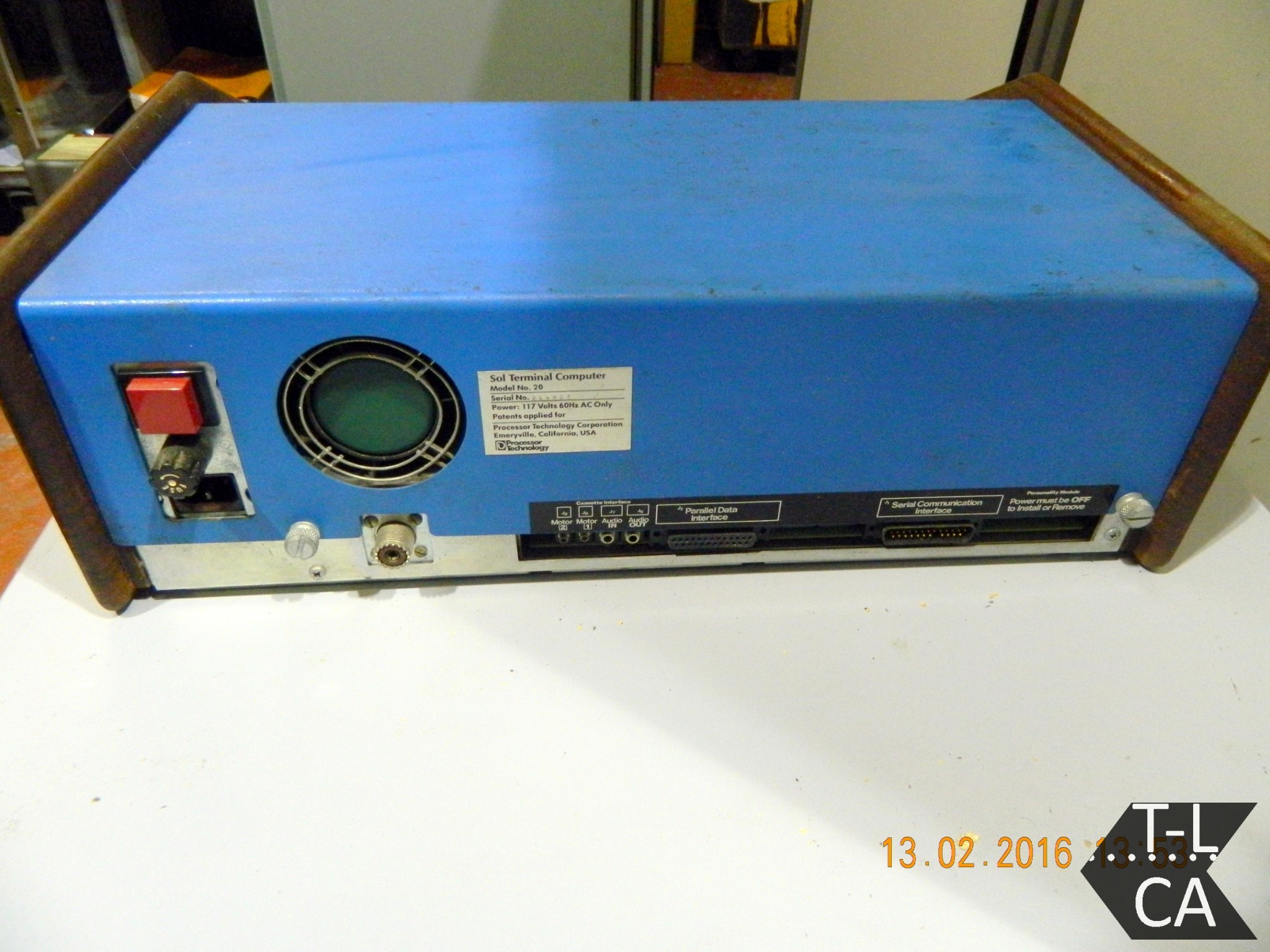
You can see that the whole left side is taken up with power supply components: power button, fan, fuse, and power cord connection. Since my reproduction does not require any of these I chose to focus on and highlight the interface section in the lower right part of the rear panel.
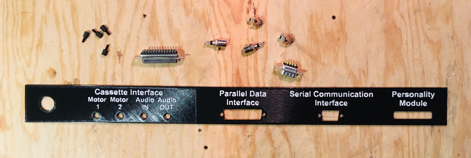
So I designed and printed my own "interface" panel and dug through my parts box for the components to populate it.
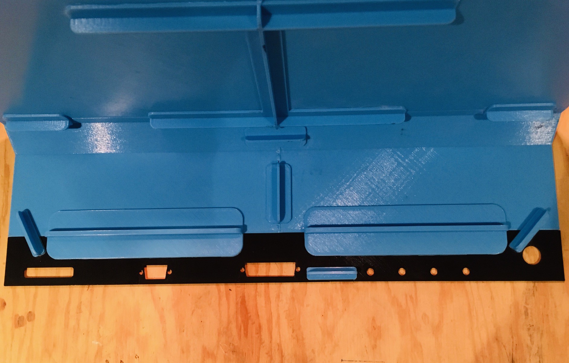
I then attached the interfaces panel to the rear panel with glue and braces.
Then I added the connection hardware. Here is what the back of my reproduction look like.
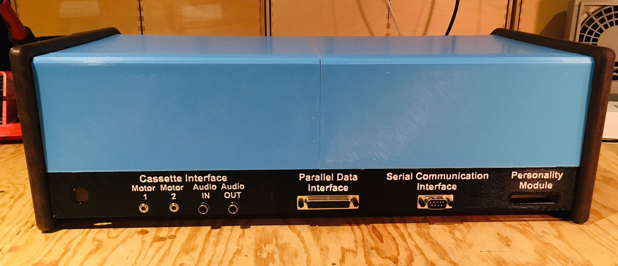
Understand at this point these ports are mostly for show. I already have a "virtual" cassette so I'm unlikely to implement a physical one. I do plan to get the serial interface working, but since I have nothing with a parallel interface to connect to, I probably won't wire that one up. While I don't plan to support real Sol-20 personality modules, I do have an idea that I might simulate a personality module with perhaps RFID tags to have the Sol-20 reproduction load different software modules on system startup. Right now the personality module slot is just a simple hole.
Discussions
Become a Hackaday.io Member
Create an account to leave a comment. Already have an account? Log In.