 kwikius
In reply to https://hackaday.io/project/181677/discussion-169393
I had another look at the mcu that I removed from my 2nd version of the car reversing kit and saw it had chip markings on the underside. (N.B 2 pictures shown as for some reason the light obscures one or other dependent on angle )The markings say:
FH511
LON.1
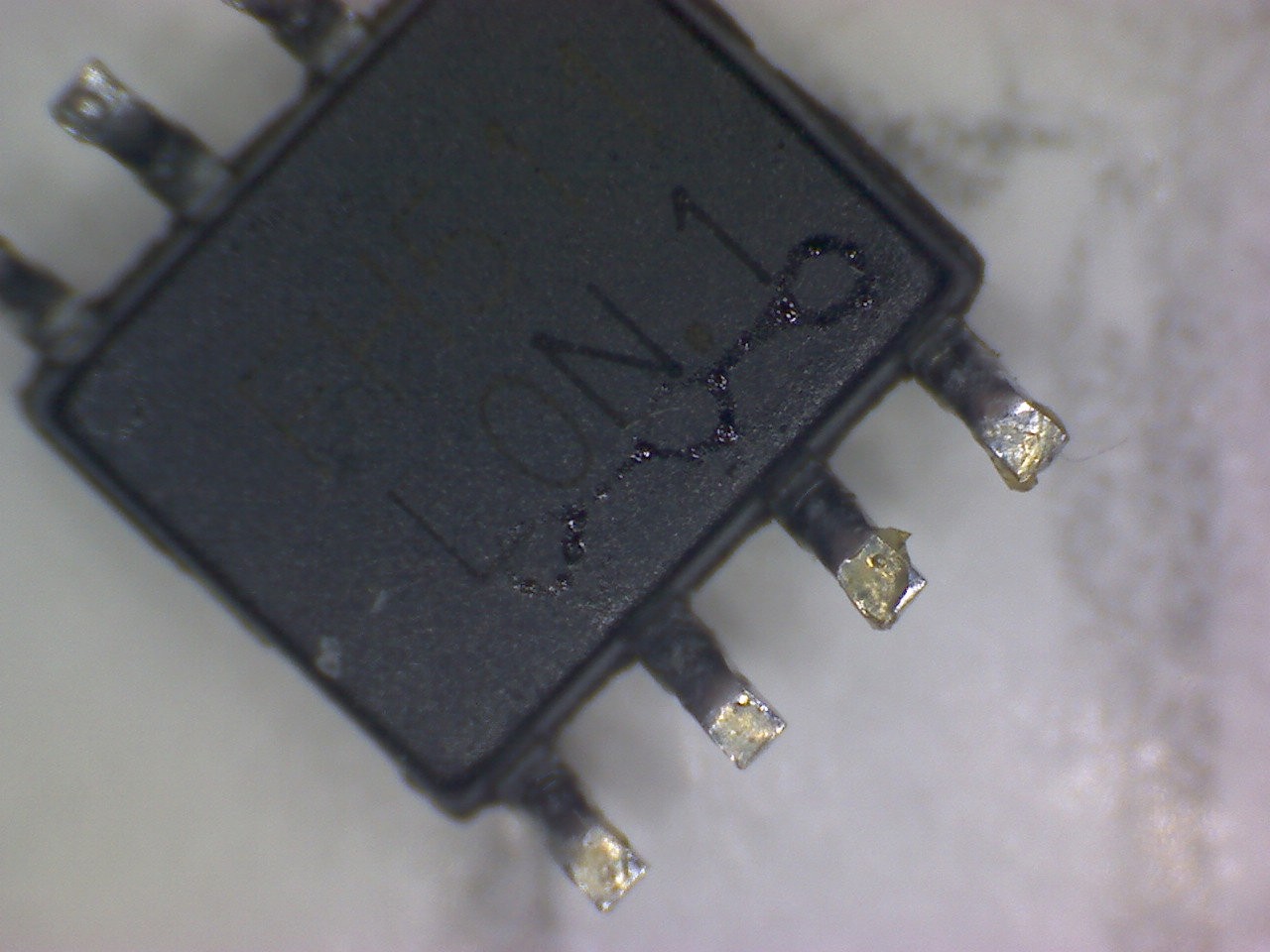
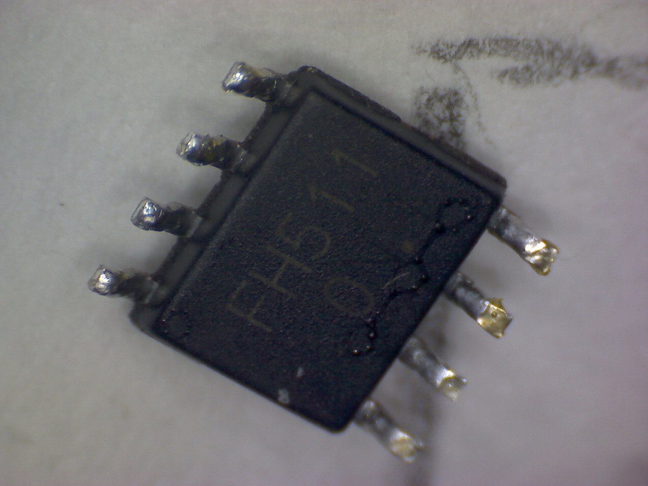
However I couldn't find anything useful by googling that!
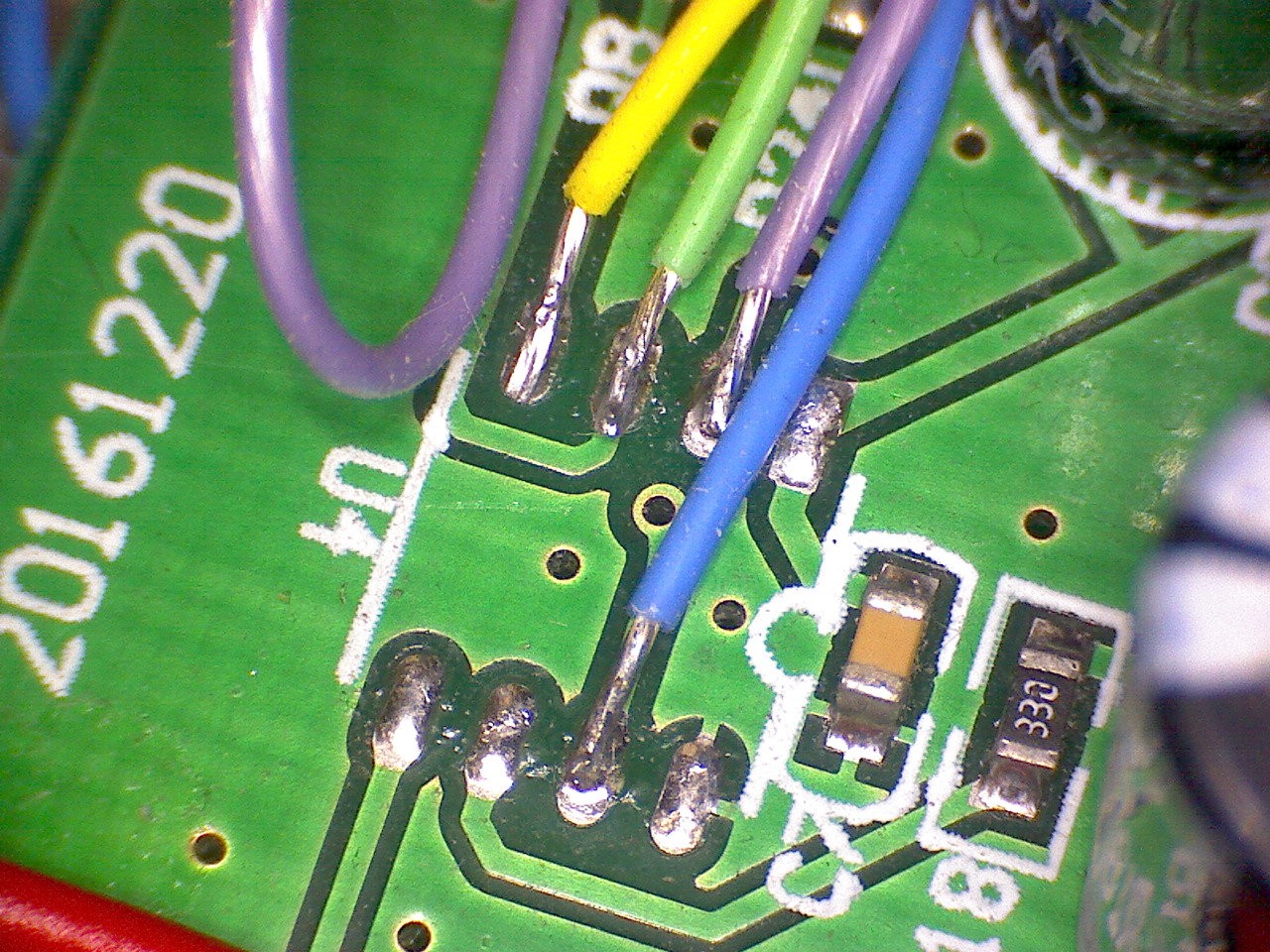
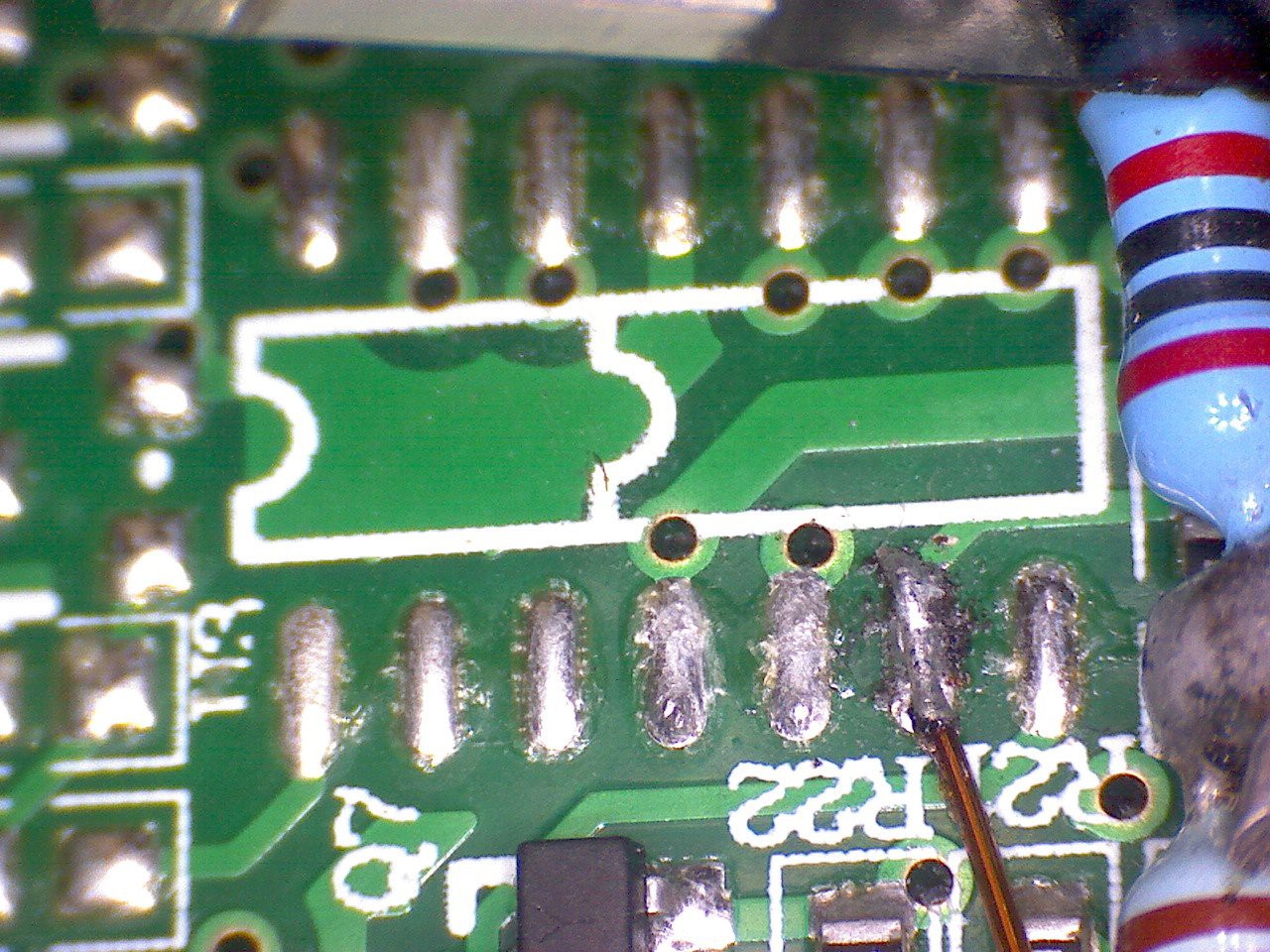
Here also are some closeups of the two footprints on the 2 different car reversing kit boards I have.
mcu footprint of first kit1 I bought
mcu footprint of second kit I bought
Here is why I think it might be a PIC12
The original MCU pinout ( based on the 8 pin footprint, but for both boards) v PIC12 footprint. I have only quickly studied the PIC12 datasheet and the pcb so data may be inaccurate!
| pin number | PCB MCU function | PIC12F function |
|---|---|---|
| Pin1 | 5V | 5V |
| Pin2 | Transducer address out bit0 | RA5 |
| Pin3 | Transducer drive | RA4 |
| Pin4 | Pulse envelope detect | RA3. T1G Timer1 (16 bit timer) gate, so could accurately capture flight time |
| Pin5 | monitor power? monitor Clk? | RA2 SCL? |
| Pin6 | monitor data IO ? | RA1 SDA? |
| Pin7 | Transducer address out bit1 | RA0 |
| Pin8 | GND | GND |
Discussions
Become a Hackaday.io Member
Create an account to leave a comment. Already have an account? Log In.