It's been a long time because my studies are taking up my time but I still wanted to share some hardware updates from about a year ago.
I started by planning, machining and assembling the actuator with the Institute of General Mechanics at RWTH Aachen:
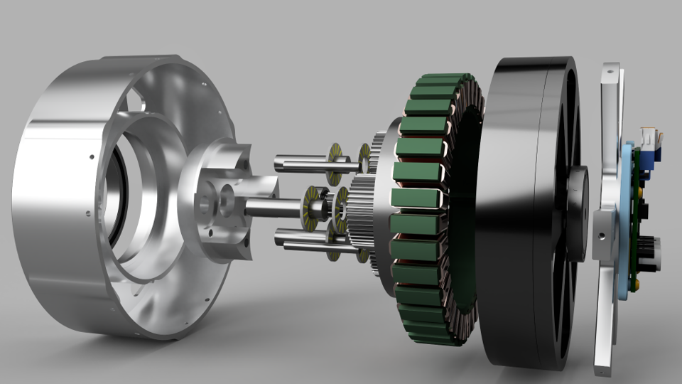
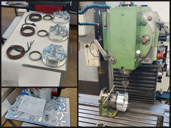
We had some fitment issues but after a few adjusted prototypes and shrink fits - and the parts finally arrived - the assembly could start:
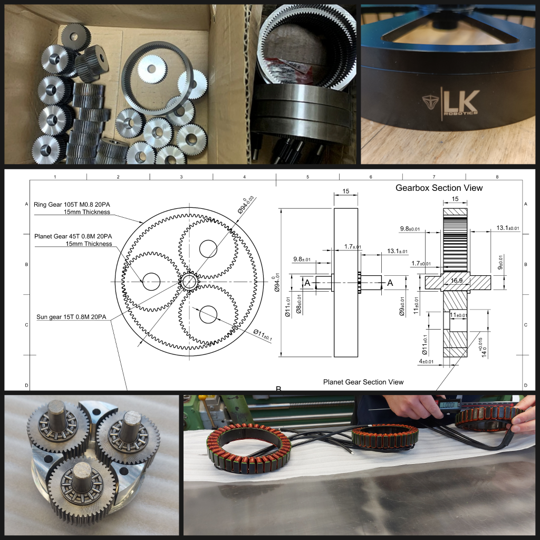
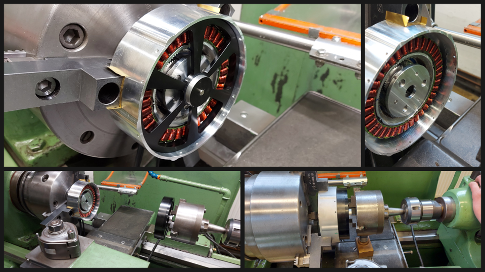
For that, we cleverly used the lathe to lower the rotor into the stator/housing assembly, which worked surprisingly well after figuring out a solution to hold the rotor with the lathe.
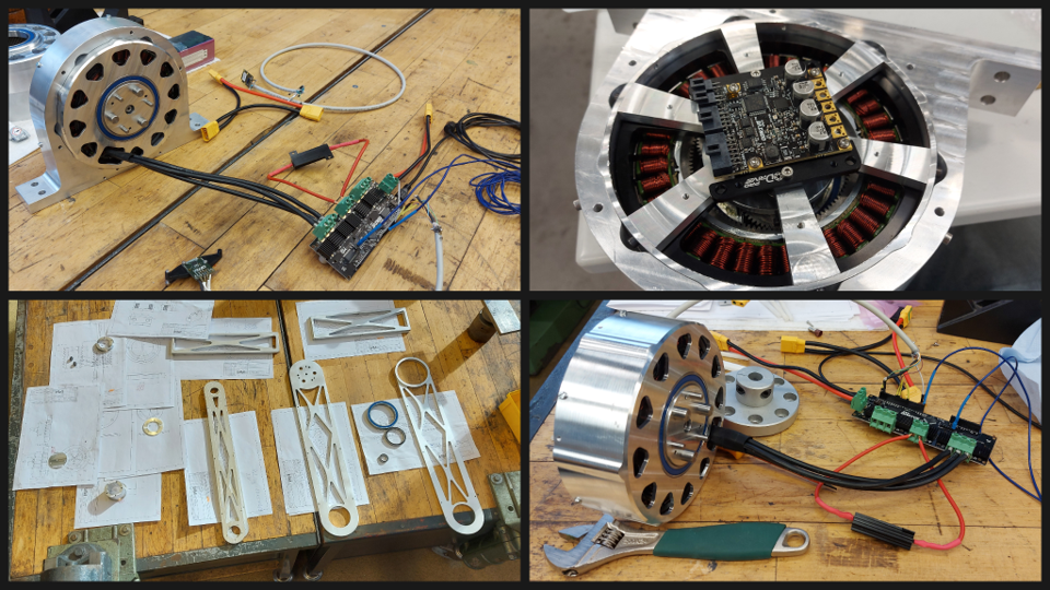
I used ODrive for servo control (as you can see whichever version I had available at the time because time was quite limited), and simultaneously machined the first leg parts (bottom left).
Keep in mind this was all done in about 3 weeks so I wasn't able to do everything perfectly. Below, you can see torque testing using a professional torque measuring jig that RWTH Aachen offered me. This allowed me to test torque commands vs. real measured torque, even under continuous rotation:
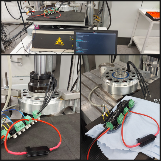
I don't have any torque plots available unfortunately but I was able to test it with 125Nm commanded for a few seconds and it did reach that value without breaking. At least after fixing the connection between sun gear and rotor because it was slipping. I did also have some encoder issues though because I was still using ODrive v3.6.
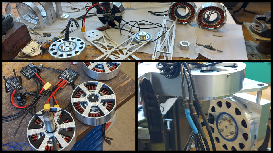
I didn't have much time to test things so I quickly moved on to building a few more actuators and assembling the leg. Just as another disclaimer, from this point on I have increasingly less detailed videos and pictures because time was *really* limited.
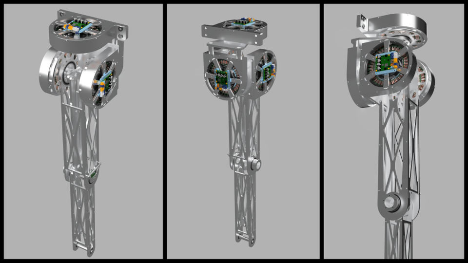
This was the current plan for a first prototype, simplified but still roughly the same degrees of freedom. I wanted to test impedance control on one leg and find out how many things I had to chance to make it work as well as it did in the simulation.
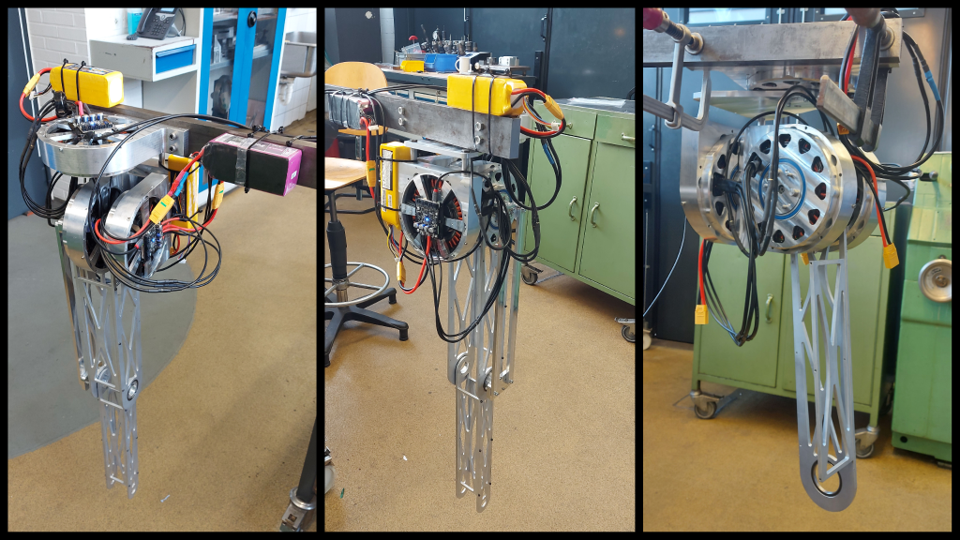
And this is it in real-life, I had to replace the planned cable-driven joint for the knee with a linkage last-minute because it was causing issues. Of course, I also had to implement a software correction for the knee angles as you can see in this video:
After a few days of troubleshooting the backlash, friction and software problems seen above, I got the same controller used in the simulation tests to move the leg in a controlled manner:
Below are the only plots I could find, just to make it a bit more scientific :)
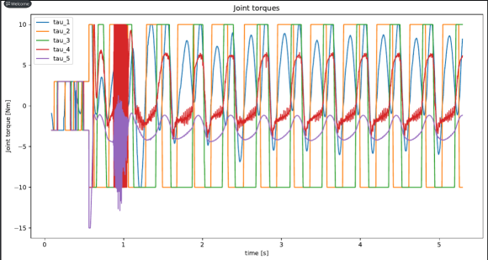
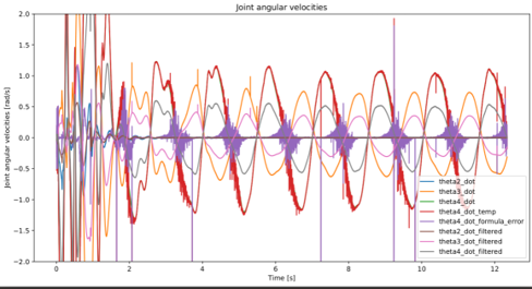
This is everything I have so far because the exams were coming up. But next would be refining a lot of mechanical issues I only patched up due while trying to get it to work, so a few mechanical redesigns and and then testing the impedance control more stable. After that I will build another leg and slowly assemble the full robot.
 Loukas K.
Discussions
Become a Hackaday.io Member
Create an account to leave a comment. Already have an account? Log In.