Release v2.0-pre1.
Finalized general board layout.
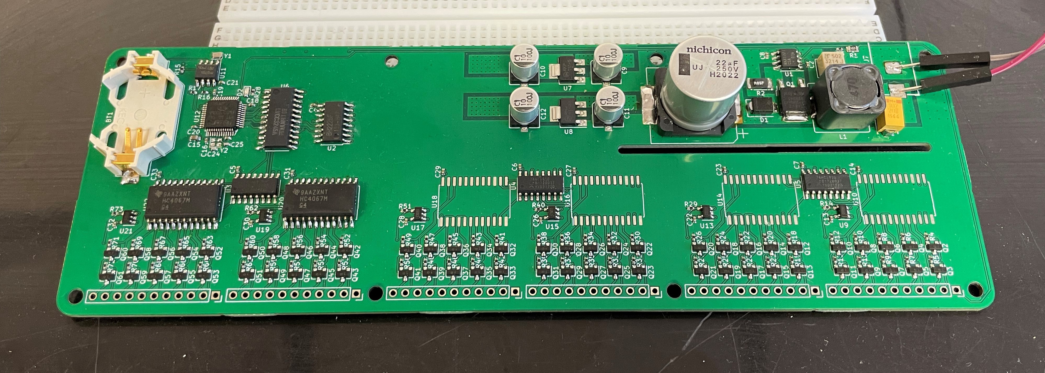
Each tube gets its own current feedback loop. Controlled by the shift registers and the DAC. Tube current can be individually adjusted (8-bit DAC) between 0 ~ 10.6 mA.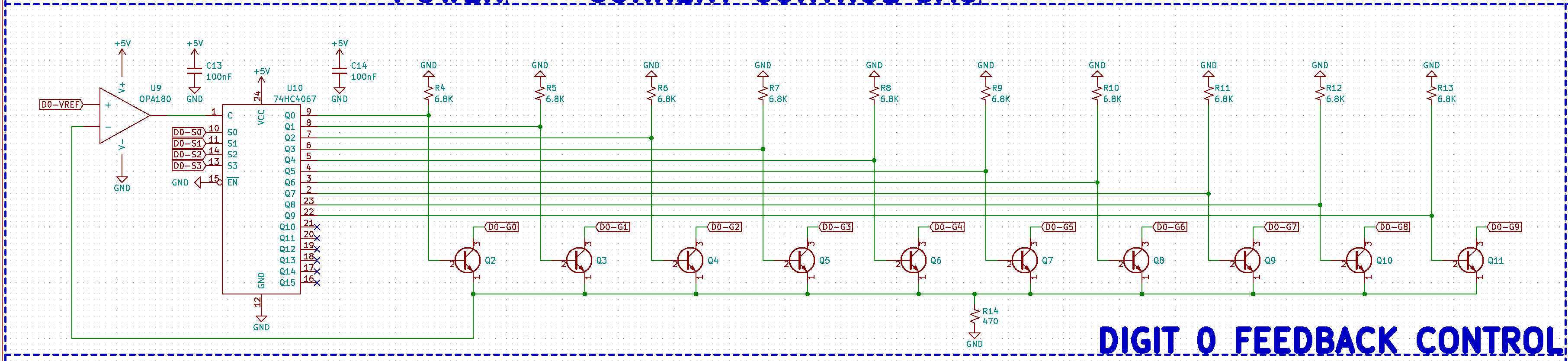
What worked:
- Power supplies (180V, 5V, 3.3V)
- Microcontroller
- Real time clock
- Level shifter
- DAC
- Shift registers
- Analog multiplexers
What didn't work:
- Current control
I messed up the footprint for the BJTs.
Discussions
Become a Hackaday.io Member
Create an account to leave a comment. Already have an account? Log In.