 RetroModder
This update focuses primarily on "productionization", including design simplification and improvements to part commonality.
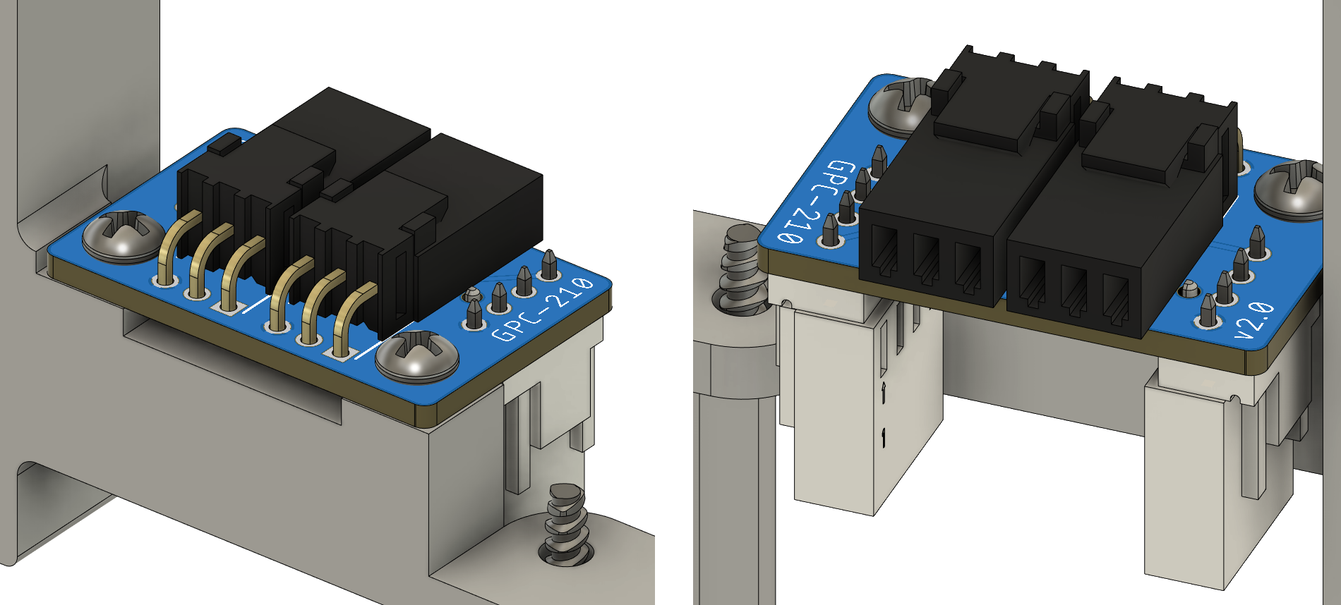
A new design for the fan header board was made to use the same 4-pin headers as on the motherboard, simplifying the wire harness from the motherboard to this PCB.
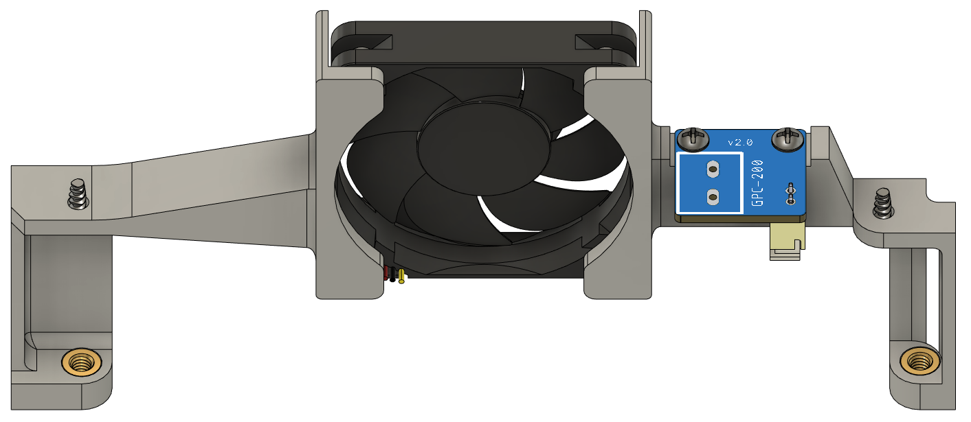
A new method of mounting the fan was experimented with. Four posts were added that the fan slides over, with the intent of using a custom-made soldering iron tip to "mushroom" the ends over and keep the fan in place. The fan was also changed to a less expensive off-the-shelf part.

Threaded brass inserts were added for the four socket-head cap screws that hold the case together. Another custom-made soldering iron tip was machined in order to install these brass inserts in the tight space.
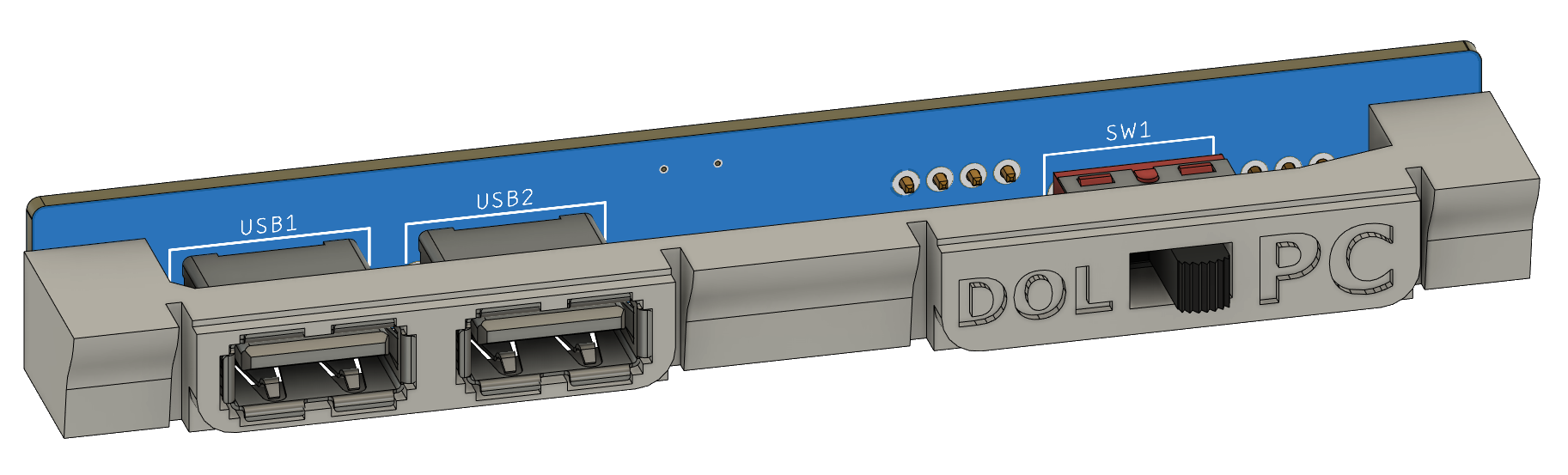
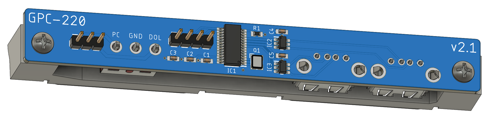
Some cleaning up was done around the front panel USB board. SMT 0805 production-ready components replaced the larger through-hole and 1206 prototypes. A previous version of the board had failed due to absorbing a shock of static electricity, so an ESD protection chip was added to prevent component damage.
Discussions
Become a Hackaday.io Member
Create an account to leave a comment. Already have an account? Log In.