Stuart MacKenzie
-
Dual switch FLAG test with FSCC
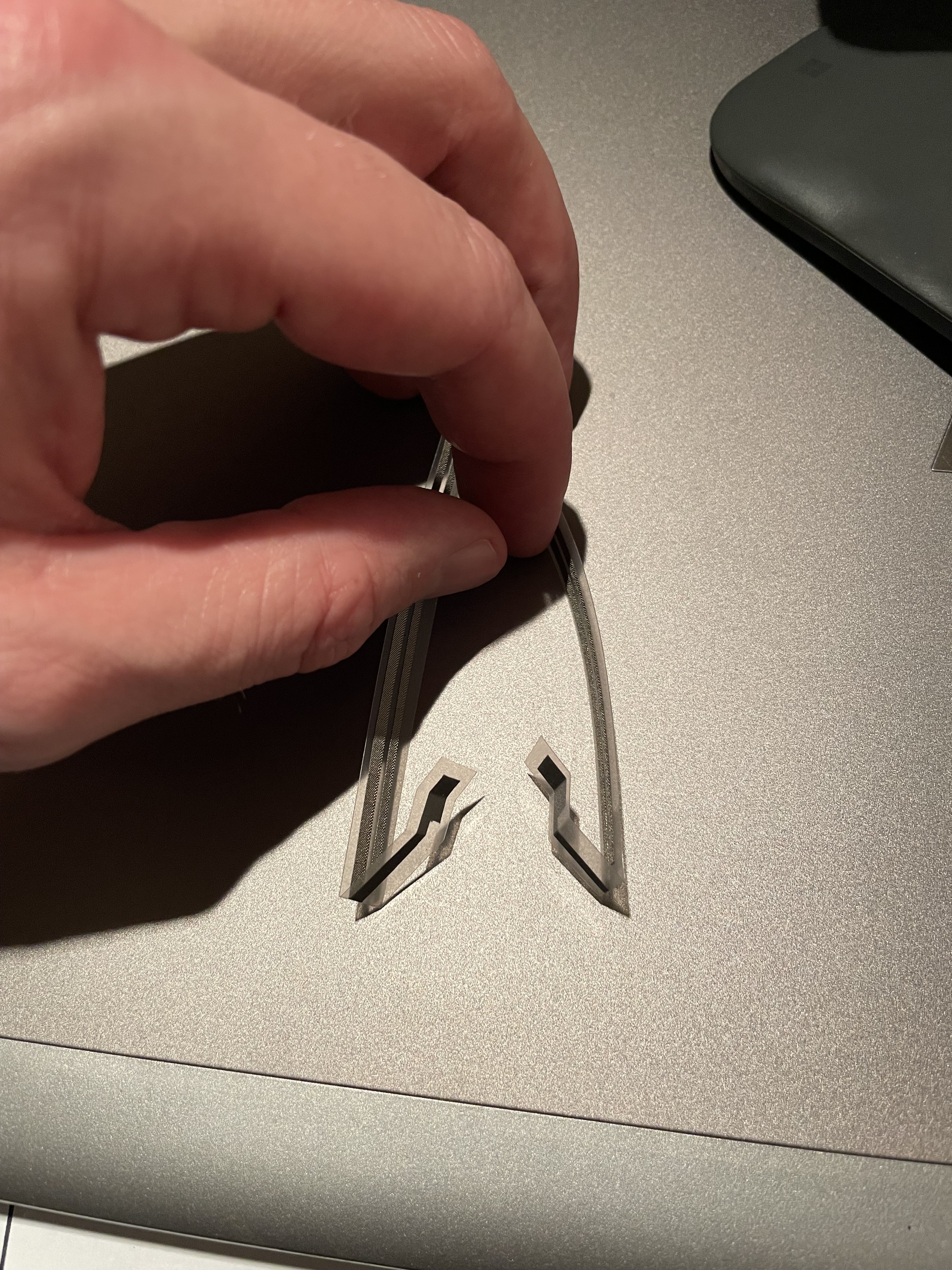
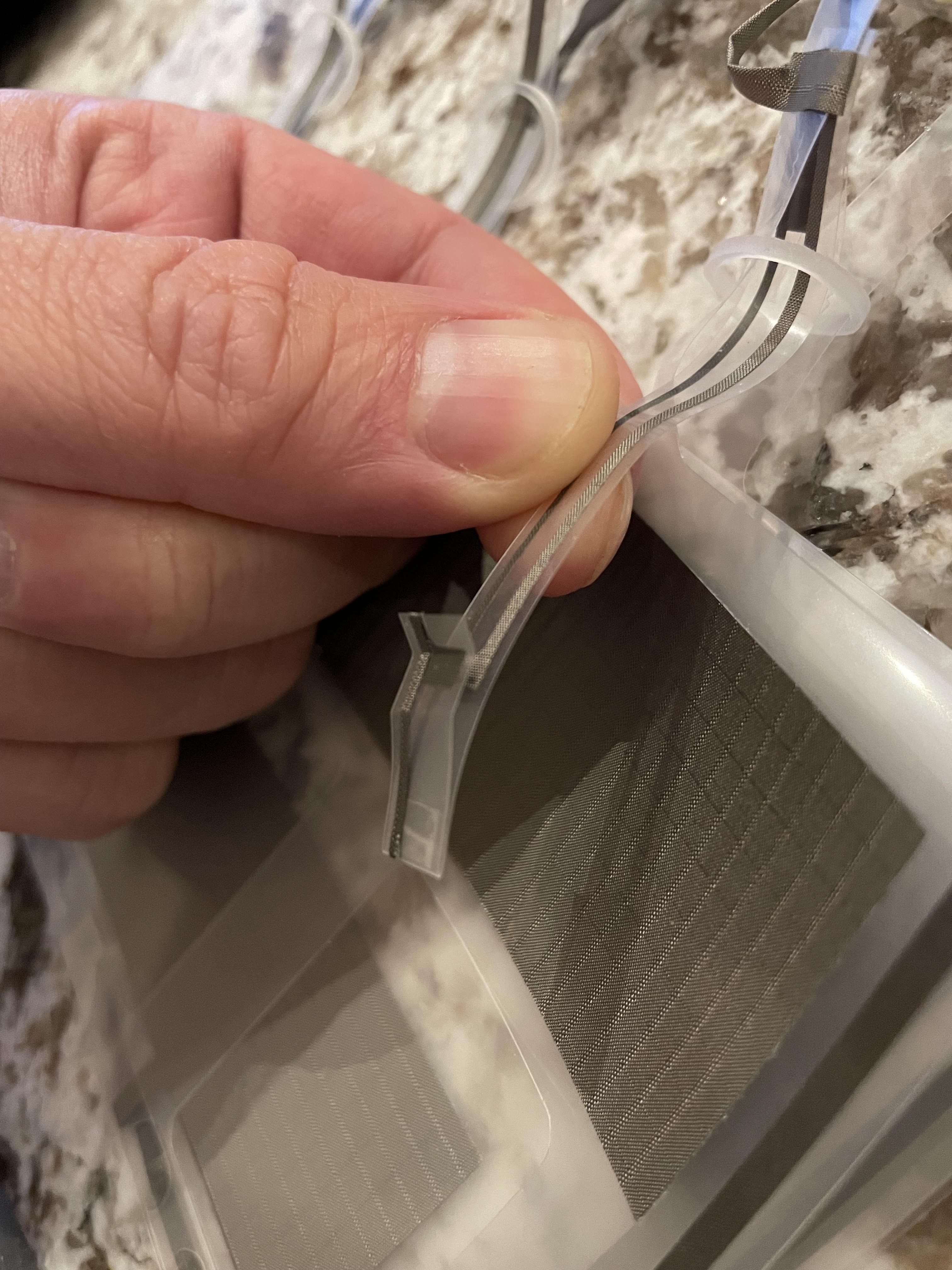
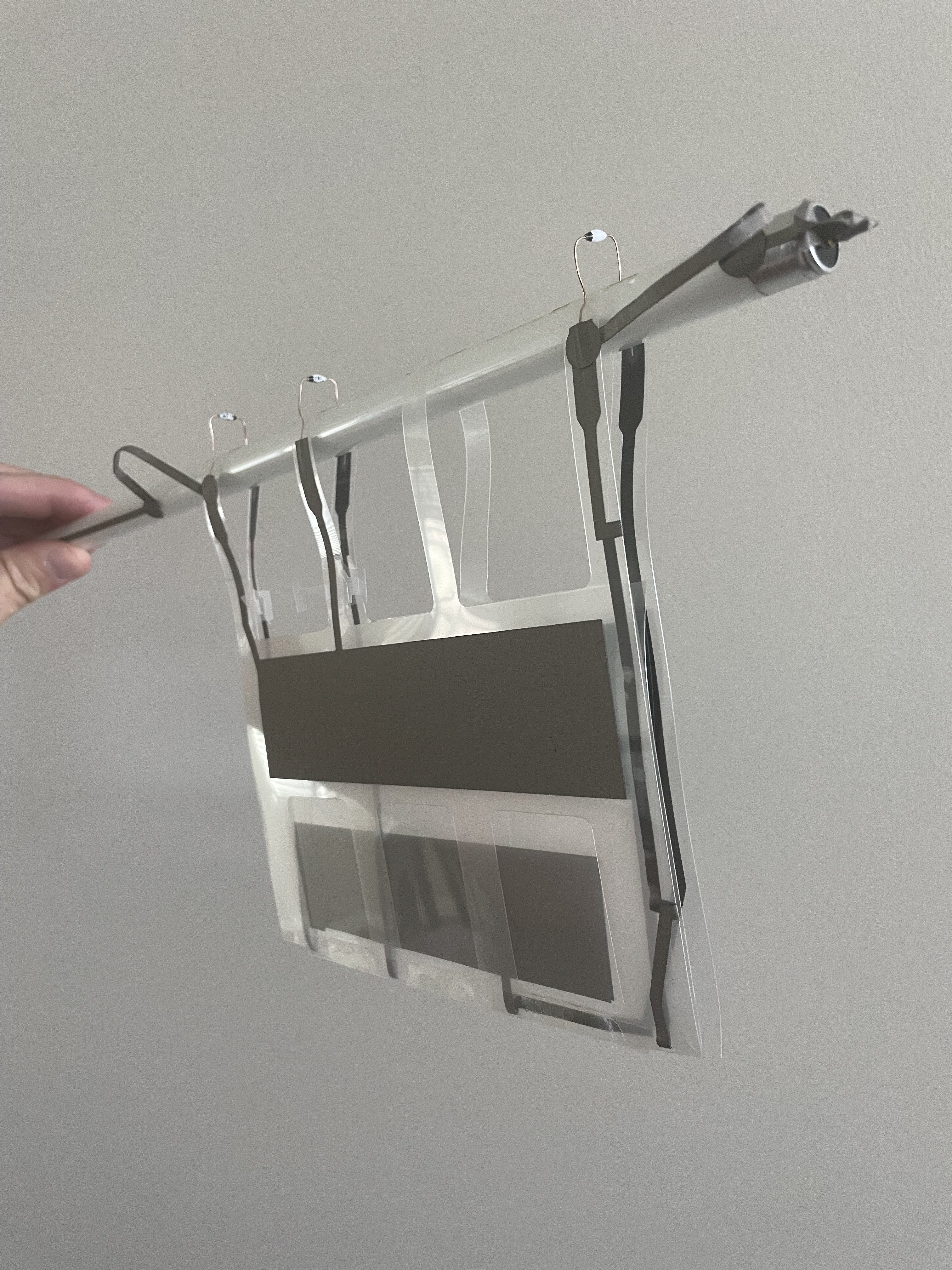
01/23/2022 at 05:37 • 0 commentsSo my previous test of the FLAG with a fractal switched capacitor circuit (FSCC) used only one switch to trigger the circuit. Ideally for the FLAG, the FSCC should be triggered at each of the end positions of the inner layer when it oscillates in the wind. This time I made a dual switch out of thin polyester film and conductive decal material. This way, the FSCC can be triggered every time the FLAG reaches either side of its range of motion. The switches were kinked again similarly to last time (a little too much kink this time I think). The kink is to ensure the switch will make good contact when it is gently compressed by the center layer of polyester against the outer layer of the FLAG.
![]()
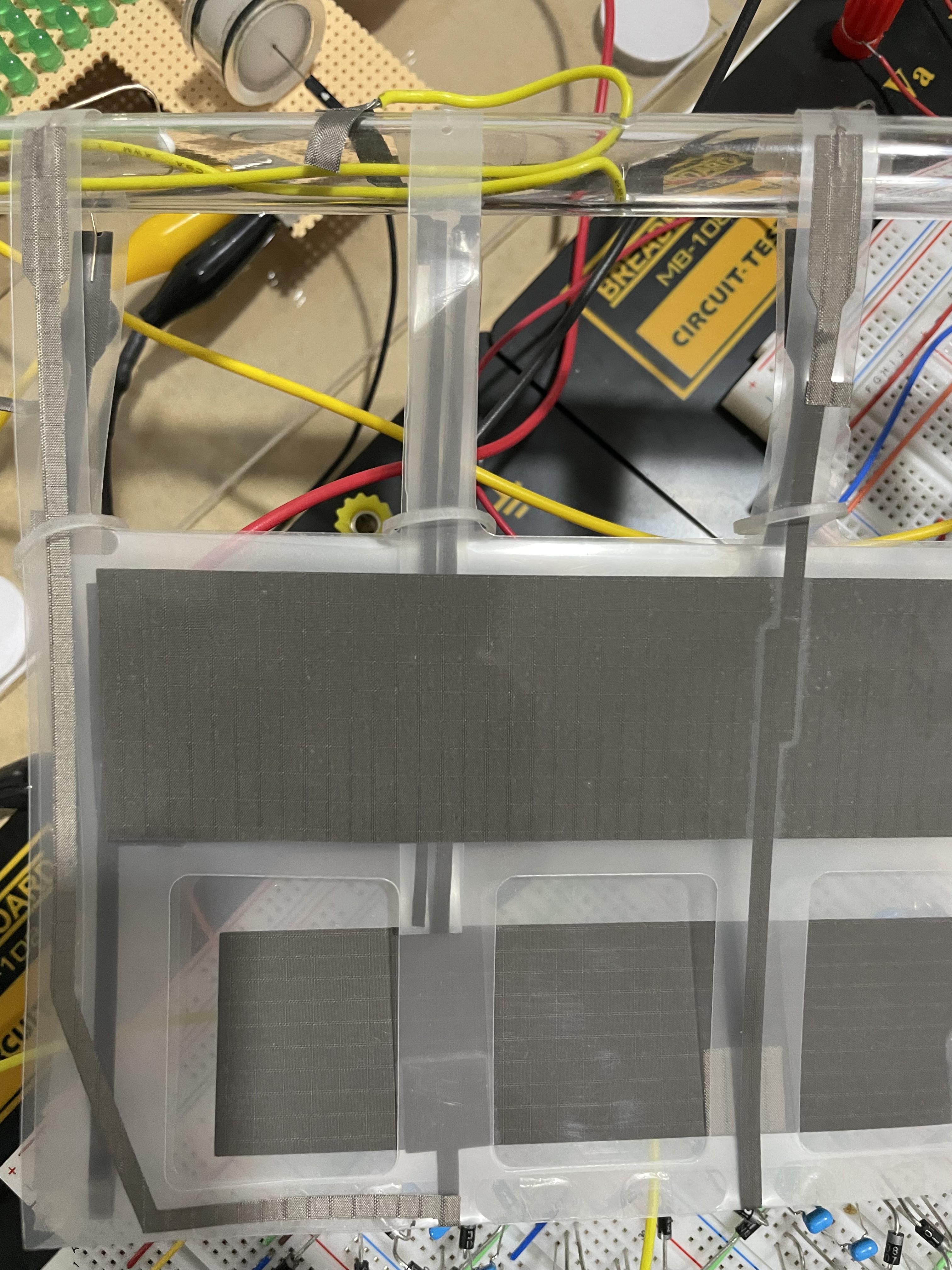
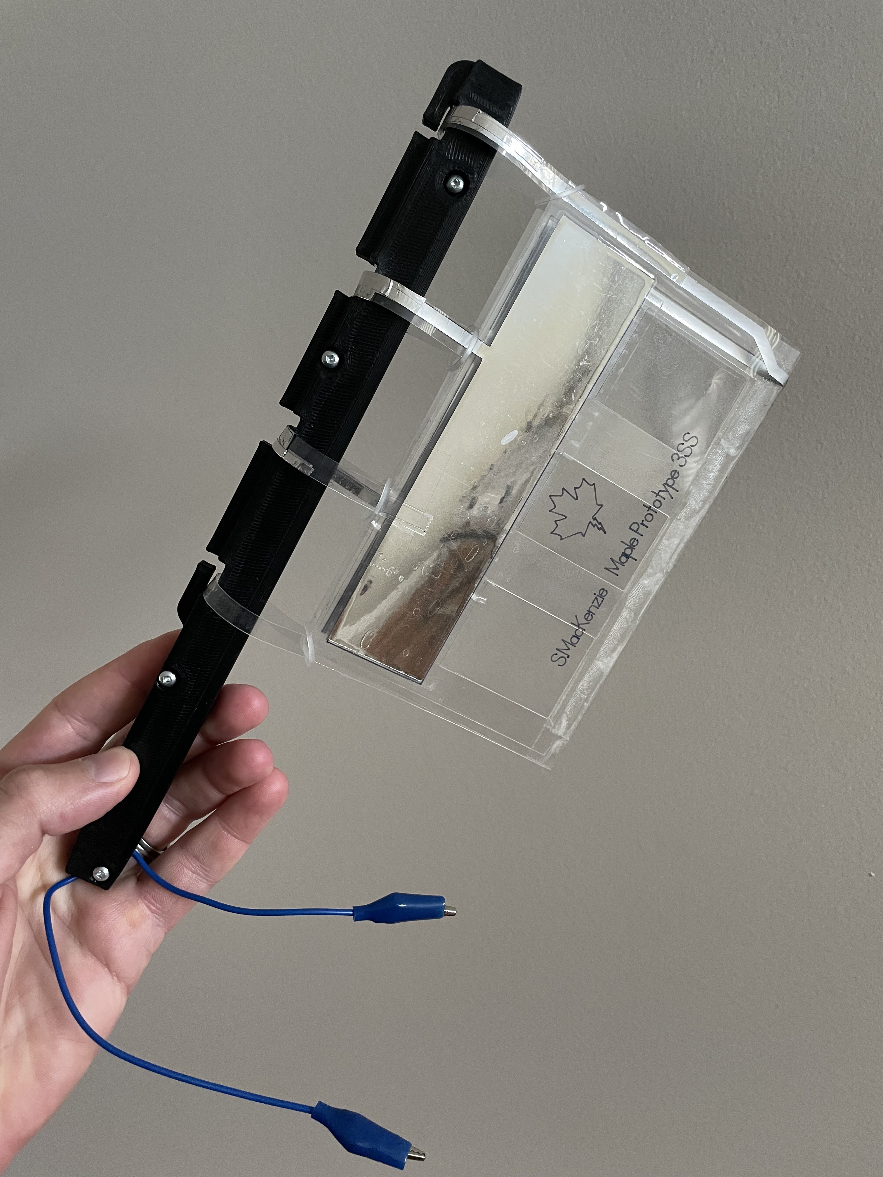
I inserted the dual switch into the FLAG, so there is a switch is on either side of the center layer. I connected it to the yellow wires, which trigger the FSCC. The high voltage current goes to the FSCC circuit through a pair of alligator clips, in the same way as before.
![]()
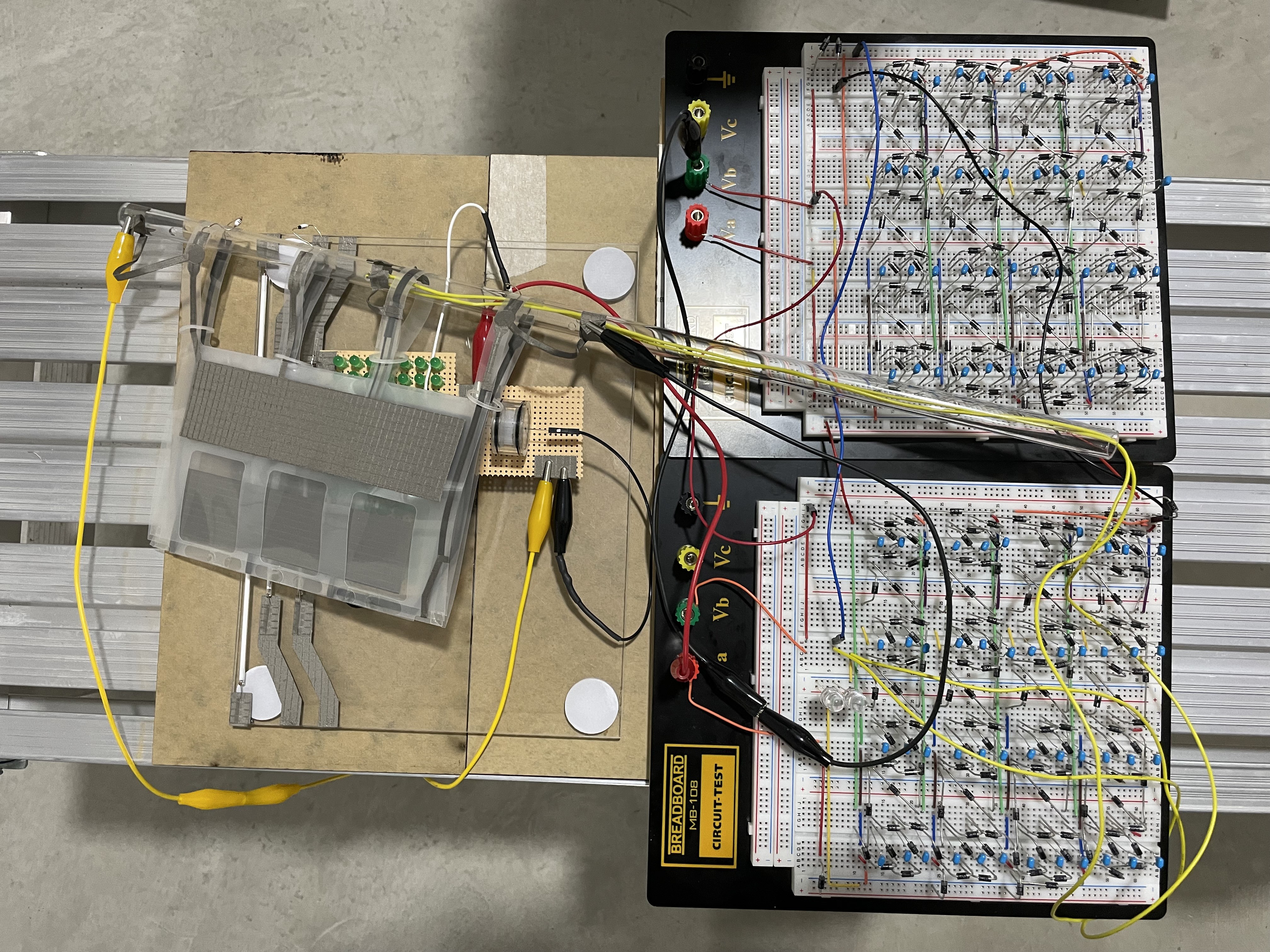
I then allowed the FLAG to oscillate with the air blower in my garage, connected to the same FSCC circuit as before. This time, I was able to light as many LED's of different colors as I could fit on my proto-board, which was 20 regular size LED's, and 2 extra large LED's. I think due to the switches being kinked too much, the switching was not occurring quite at the perfect time, so the brightness was not quite as good as the previous test. Nonetheless, the blinking frequency looked much faster with the dual switches (it looked borderline like being continuously lit at times), and I was able to light up more LED's. It looked like the FLAG could have lit even more, though probably not as many as it can light in series without the FSCC at a few hundred volts. Using all identical LED's also would likely have worked a lot better.
-
Fractal switched capacitor converter testing #1
11/10/2021 at 07:05 • 0 commentsThe FLAG prototypes are able to light at least 98 LED's wired in series, fluorescent lightbulbs, or any loads that like a high-voltage-low-current output. Wouldn't it be nice to convert the FLAG output to a low-voltage-high-current output for powering electronics, or to trickle charge a small battery? Historically this conversion has been difficult to do efficiently for influence machines.
Just in time, comes the invention of the FSCC (Fractal Switched Capacitor Converter)! This converter circuit was developed at Chongqing University for a different type of generator with a similar output to a FLAG. The FSCC charges capacitors in series, and discharges them in parallel, in such a way that it works like a transformer, at high efficiency (94%), and with minimized voltage drop from the diodes.
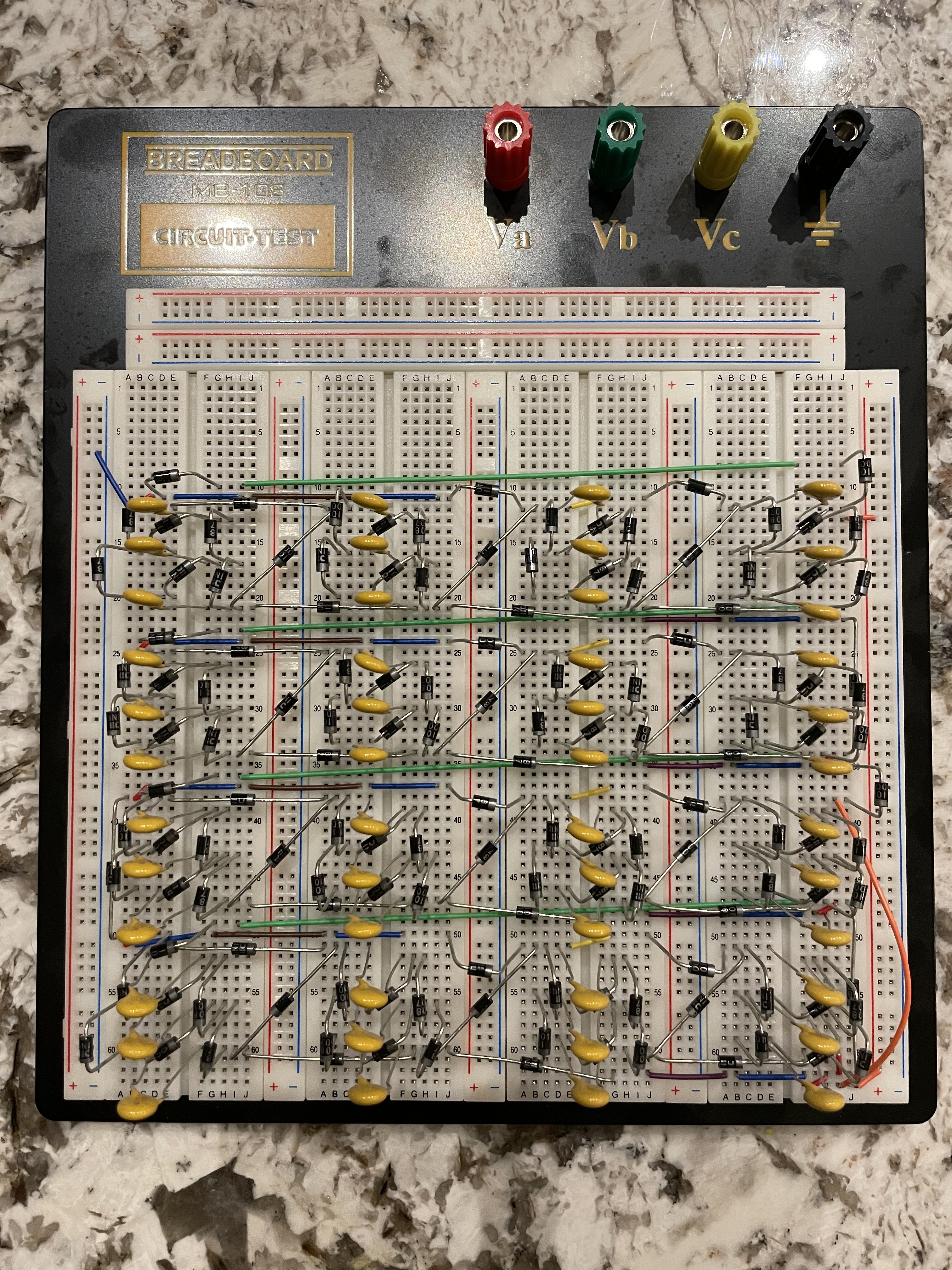
I ordered the diodes (1N4007) and capacitors (22nF) from Digikey, and built the 96 unit FSCC converter circuit from the paper on a breadboard, to give it a try with the FLAG. To operate, the FSCC requires that a switch is contacted on every stroke of the FLAG, so I made a small flat switch that fits inside the FLAG. Ideally, it should be contacted at the moment the inner layer is flat against the outer layer. With all the effort I went through to remove the surface contact switches from the FLAG, I'm not thrilled to add one, but this is just a test to see if this new type of transformer will really work. Below is a picture of the switch- it is folded over and bent with a small kink in it so that it will stay open until the FLAG squeezes it a little each oscillation, closing the circuit.
![]()
Before the FSCC, the FLAG could not light any LED's in parallel- it only makes enough current to light a lot of LED's in series. On this first attempt, the FSCC allowed the FLAG to light 17 LED's in parallel including 2 large LEDs (12 shown in the below video). I find this hugely exciting! With a properly designed FSCC, FLAGs will be able to efficiently produce any voltage required, at high efficiency.
I could see in this test, it was important for the switch to open and close at the correct time and with good contact, which was affected by the angle and amount of kink that I put into it. When I gave the switch too much kink, the LED brightness would decrease. Ideally the switch should be removed completely and replaced with a solid-state solution. In my attempts to make adjustments to the switch, I unfortunately damaged it before I could make any measurements, but that leaves something fun for next time.
Even the tiniest movements of the film caused the LED's to light, which is also exciting for future developments. The first FLAG attempts operated at very high frequency and were held under some tension, with more of a vibration like motion at approximately 50Hz and only moving a couple of millimeters. I can see how operating the FLAG under tension like that would increase the power output- perhaps by a factor of 5, since that would be the relative increase in oscillation frequency. The shorter stroke would also mean that more layers could be fit into the same volume (another multiplier for power output per unit volume). Higher frequency designs seem well suited for kites, which by their nature are held in tension.
As this FSCC was not custom designed to match the FLAG output, I'm sure the efficiency could be improved. It should also have two switches, one for each of the two end positions of the center layer of film. That means the LED's in this test were blinking half as often as they would with two switches. In the future, I would like to try this again with two better designed switches, and a slightly smaller FSCC.
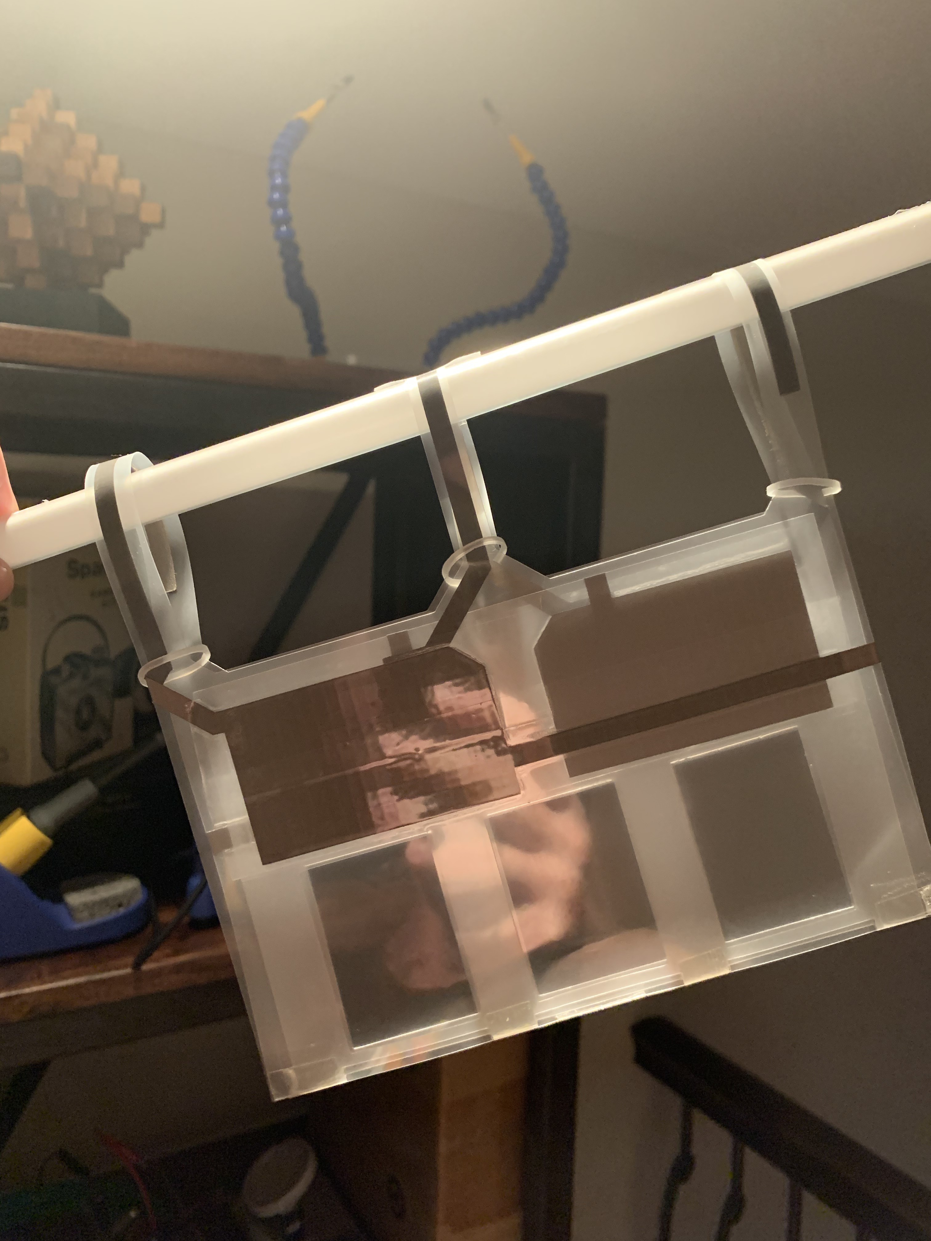
Below is an image of the apparatus from this test. You can see the 96 unit FSCC took two poorly-planned breadboards, although Chongqing University fit the same circuit onto one relatively small PCB. The FLAG has been mounted onto an acrylic tube, and the two small yellow switch wires were run through the tube, and connected to the FSCC. The FLAG outputs are connected to a small spark gap and the FSCC through the alligator clips. A couple of the large blue LED's that were blinking in the video can be seen in the bottom breadboard. The FLAG was then exposed to approximately 20km/h air from a nearby blower to energize the FSCC circuit.
![]()
-
Cutting machine files
10/30/2021 at 16:23 • 0 commentsThe links to the Cricut cutting machine files are in the assembly instructions PDF, but they are also included below. In order to use these, you would need a Cricut cutting machine, and to have Cricut Design Space installed.
I am not aware of a way to directly convert these Cricut files to the SVG file format for other cutting machines. If you have a different type of cutting machine, I think it would be necessary to open these files in the free Cricut Design Space software, print them as images, and then convert the images to SVG. If you prepare the SVG files, please send them to me so I can make them available for others here!
-
FLAG Project History #10
10/14/2021 at 07:04 • 0 commentsI have been discussing FLAGs with companies that may be able to produce them with improved manufacturing using conductive-inks and other flexible printed circuit technology. I am looking forward to seeing FLAGs that have the somewhat natural appearance of leaves, or multi-cell, multi-layer designs, with higher oscillating frequency, and fully encapsulated designs to increase the power output.
One of the greatest advantages of the FLAG is that this type of design is extremely lightweight. Even the converter circuits required do not use heavy coils and magnets. Time permitting, I would like to make the first flying FLAG kite...! It will be interesting to see how far the idea can be pushed.
I am also experimenting with circuits that will efficiently convert this type of high-voltage-low-current output, to more useful low-voltage-high-current output. Traditional coil transformers do not work well in this application. The type of circuit needed was recently invented and demonstrated at high efficiency (Fractal Switched Capacitor Converter), and an attempt to make a similar converter circuit for the FLAG is in progress:
![]()
I do not really have the right measurement equipment to properly size the components of this circuit, so I am using the highly advanced method of trial and error. It is not immediately obvious from the Fractal Converter paper (which was developed for a different type of generator with similar output characteristics), but it requires a switch to trigger the circuit at the right moment of the FLAGs motion. I have had some mild success but it is not yet working as well as I would like, and I would prefer to come up with a design that is entirely solid state.
-
FLAG Project History #9
10/14/2021 at 06:58 • 0 commentsIn order to make FLAG experimentation accessible to people without 3D printers, I developed the design that was submitted for the 2021 Hackaday Prize. It can be made with only a sharp knife, plastic film, conductive tape, and 3 suitable diodes. If you have a Cricut cutting machine or know somebody with one, it will be a much quicker way to cut out the pieces and links to the Cricut files are provided in the instructions. The simplified design has a downside in that it can put repeated bending stress on the diodes, and the leads on some diodes will occasionally break. I'm sure somebody will come up with a better way to mount the diodes that will still not require the 3D printed parts.
![]()
The Hackaday Prize FLAG design has been tested outside in humid conditions:
![]()
And this design has even mounted to my truck antenna to go for a drive, with a little bit of foam to make sure it wouldn't short out on the antenna:
![]()
![]()
-
FLAG Project History #8
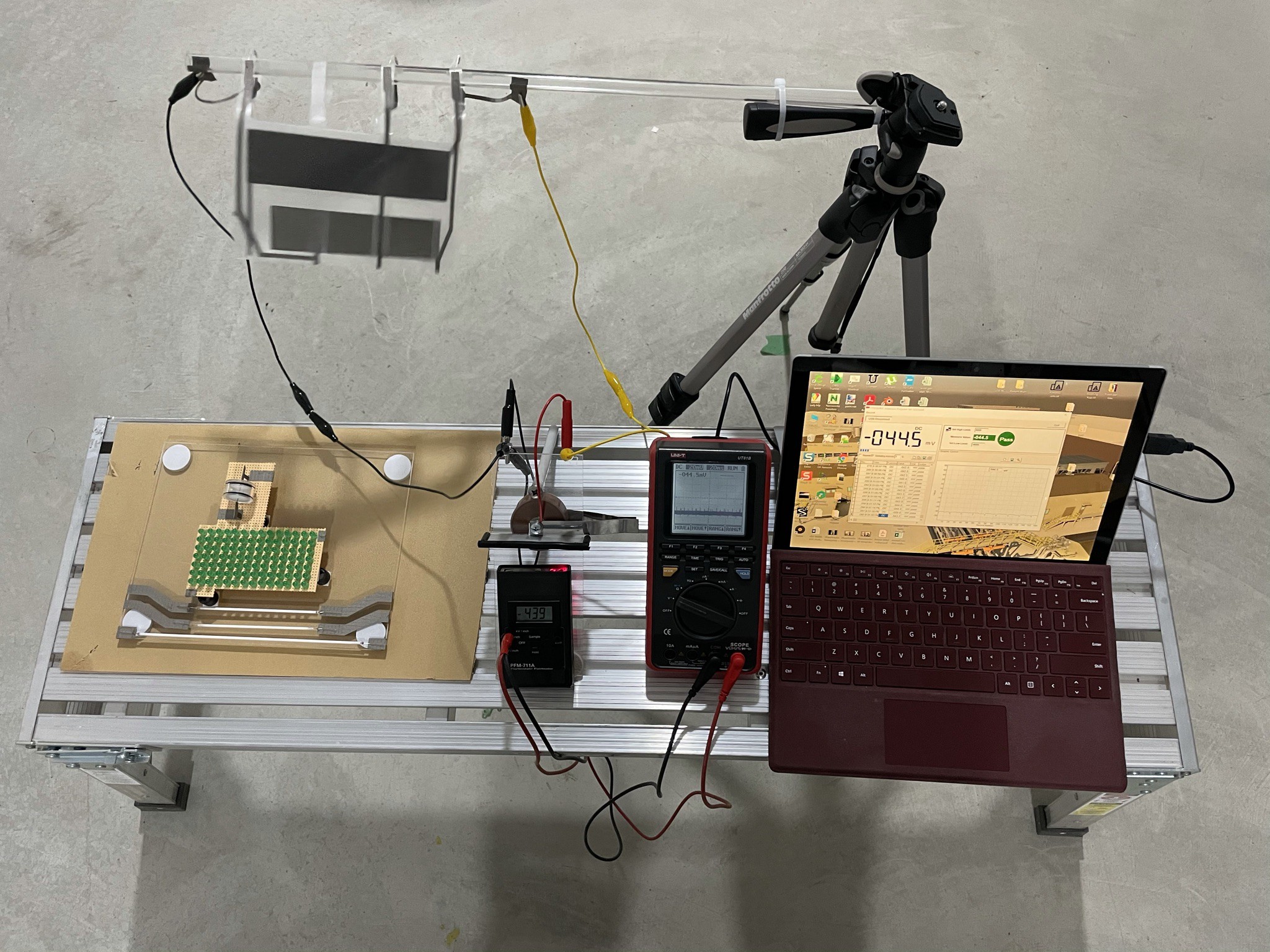
10/14/2021 at 06:44 • 0 commentsHere is a picture of the test apparatus I set up to make some measurements of the FLAG output. You can see my electric field meter near the center which I bought off ebay many years ago (and I have great doubts about its calibration and accuracy). I have it mounted 1" from an aluminum plate which is charged by the FLAG, and is also connected to a large TDK UHV-2A ceramic capacitor so I can calculate the output current by seeing how long it takes to charge the capacitor with the FLAG while monitoring the voltage with the electric field meter. The electric field meter is connected to my multimeter, which is connected to my laptop with an optical connection so the data can be recorded on my computer without risk of accidentally exposing it to the high voltage output of the FLAG. The fieldmeter is a Prostat PFM-711A.
![]()
-
FLAG Project History #7
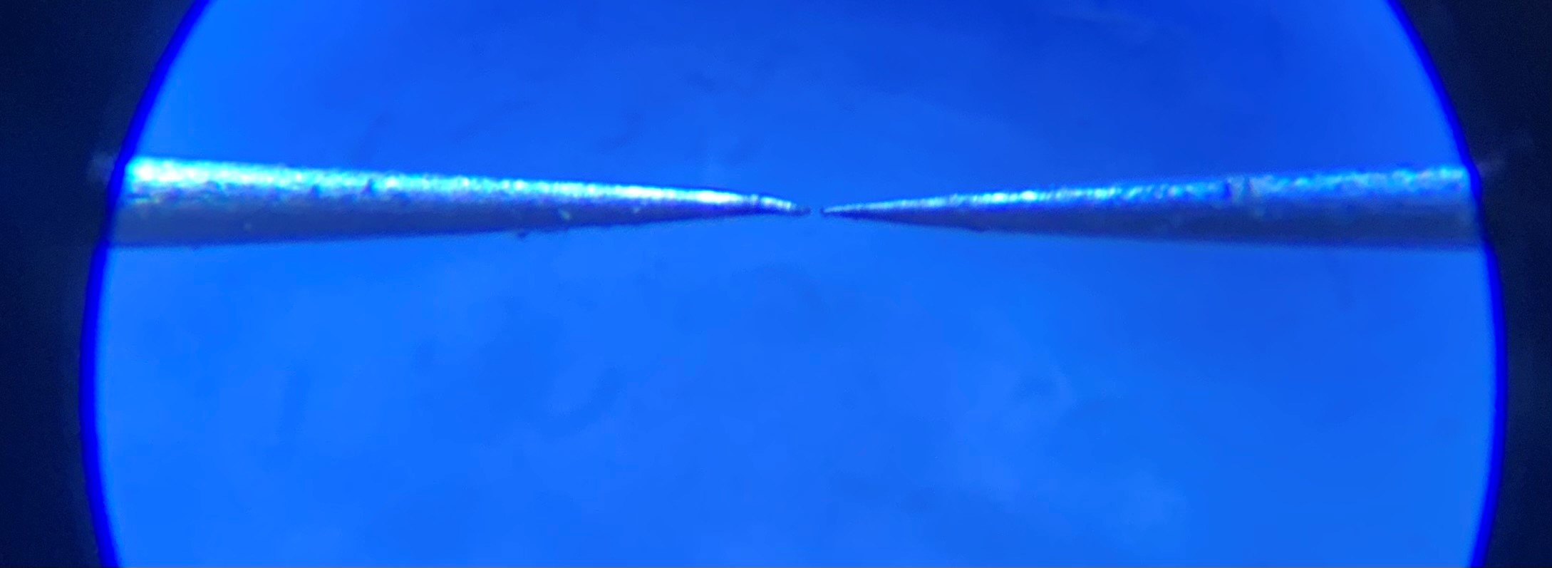
10/14/2021 at 06:33 • 0 commentsI really wanted to demonstrate the FLAG powering loads other than fluorescent light bulbs, so I set about getting it to light up LED's. LED's act a little more like a direct short across the generator output terminals, so it is necessary to put them in series with a spark gap so that there is enough load on the generator to keep it operating at high voltage. There have recently some interesting publications about using very small spark gaps to improve the performance in electrostatic harvesting systems (Plasma Switch), so I ordered some ultra-fine tip tungsten needles (0.6 µm radius tip) and machined a mount for them out of nylon. Under a microscope I carefully adjusted the gap, and I have been using this spark gap to light my LED's ever since (picture below). Prior to doing this, I have used a much more ordinary spark gap using a couple bolt heads, and it worked fine as well. In case you're wondering why one of the tungsten needles is a little bent in the below photo, I accidentally dropped it while putting this together, and had to straighten it again. When the FLAG is lighting the LED's through the needles, you can see a nice glow emanating coming from the tips.
![]()
Here is a picture of 98 ordinary LED's being lit in series (blinking at about 10 Hz, partial brightness). This was my first attempt, so I do not know the maximum number of LED's that can be lit in series with a FLAG:
![]()
-
FLAG Project History #6
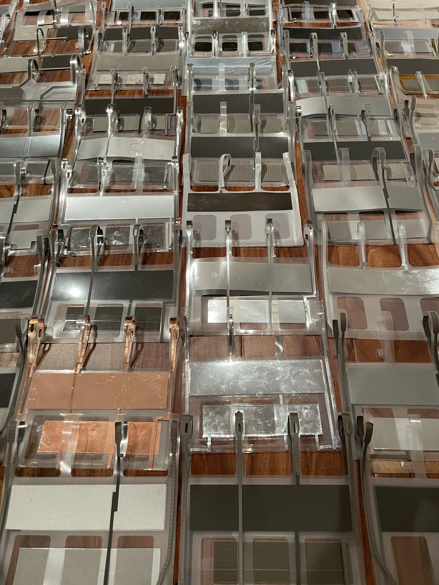
10/14/2021 at 06:29 • 0 commentsTrying to identify the causes of success and failure, I built over 200 prototypes, using different designs and materials.
![]()
What I eventually realized, was that plastic film materials intended for printing cannot be used. The pre-treatments given to plastic for printing seem to cause adsorption of humidity from the air, giving them poor surface resistivity. I also discovered problems with insulating the generators with tape. My theory is that charges migrate through the tape adhesive, and build up there- creating a parasitic capacitance with the sectors that eventually stops the machine.
Using no insulating tape, and only insulating using polyester film, I started to get consistent results. I carefully designed the generator so that all the oppositely charged conductors are on opposing film surfaces, or have a large distance between them. These two things combined allowed the generator to be self-starting at up to 60% relative humidity, and with a "jump start", it will run at higher. I believe the power output can be increased significantly by encasing the sectors within the polyester, but this sort of manufacturing is beyond what I can do at my desk.
-
FLAG Project History #5
10/14/2021 at 06:25 • 0 commentsThe poor humidity performance and unreliable switching was persisting, so at this point I decided to get rid of the surface contact switches altogether and replace them with diodes. I also changed the design to get better separation of the oppositely charged areas, and started trying different materials and insulating the generators with tape. I also bought a Cricut cutting machine to make the generators more quickly with the time I had available. I tried some designs with the diodes housed in a 3D printed mast, and very simple 3 or 4 diode harvesting circuits. This is a 3-sector design, with no storage capacitor:
![]()
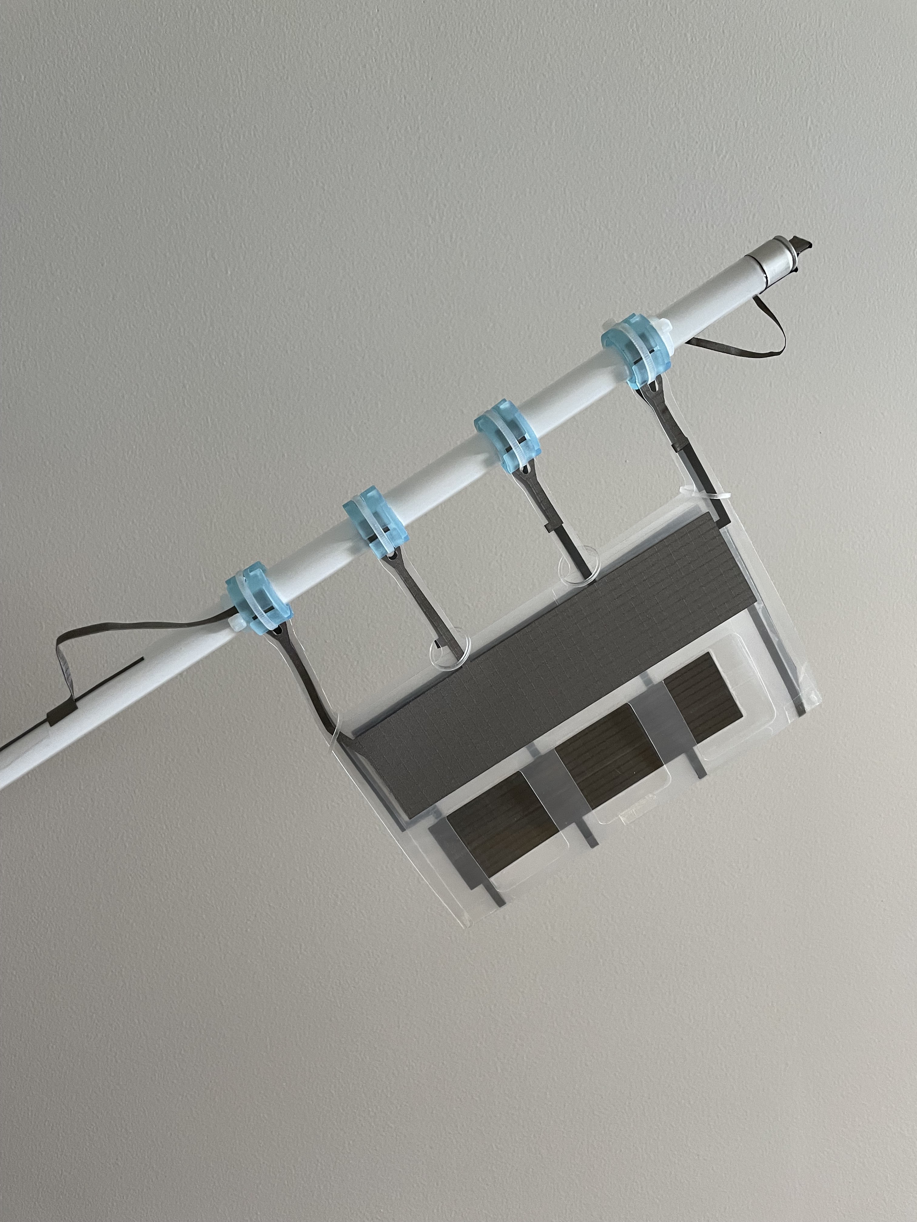
The design later progressed to having the diodes mounted in small 3D printed swivel rings that can slide over the fluorescent light itself, or over a piece of acrylic tubing if I want to try powering some other kind of load. The rings are 2-pieces, and are put together with a small zip-tie, which squeezes the ring a little bit and pinches the electrical connections between the diodes and the conductive film. You can see on these generators, I'm using small elastic bands to restrict the distance that the generator opens in the wind. One nice thing about this design, is that the electrical connections are secure, and there are no sliding contacts or subject to repeated stress. The use of diodes instead of surface contact switching allowed for a design with all the oppositely charged surfaces to be very physically separated, which really improved the performance in ordinary air humidity. Variations of this overall design are still among my favorites, but they require a high resolution 3d printer:
![]()
-
FLAG Project History #4
10/14/2021 at 06:07 • 0 commentsAfter the first successful prototype, I started making more generators in this style, mostly by hand. I refined the design a little bit; I gave it some supports so it could be hung from an acrylic rod or directly from a fluorescent light. I also put the power output on those supports, so I would no longer need to use alligator clips when testing. Here is an example, where you can see the power outputs (+ and -) on the outside supports, and the "ground" connection (approximately equivalent to a "neutralizer" on a Wimshurst machine) on the center support.
![]()
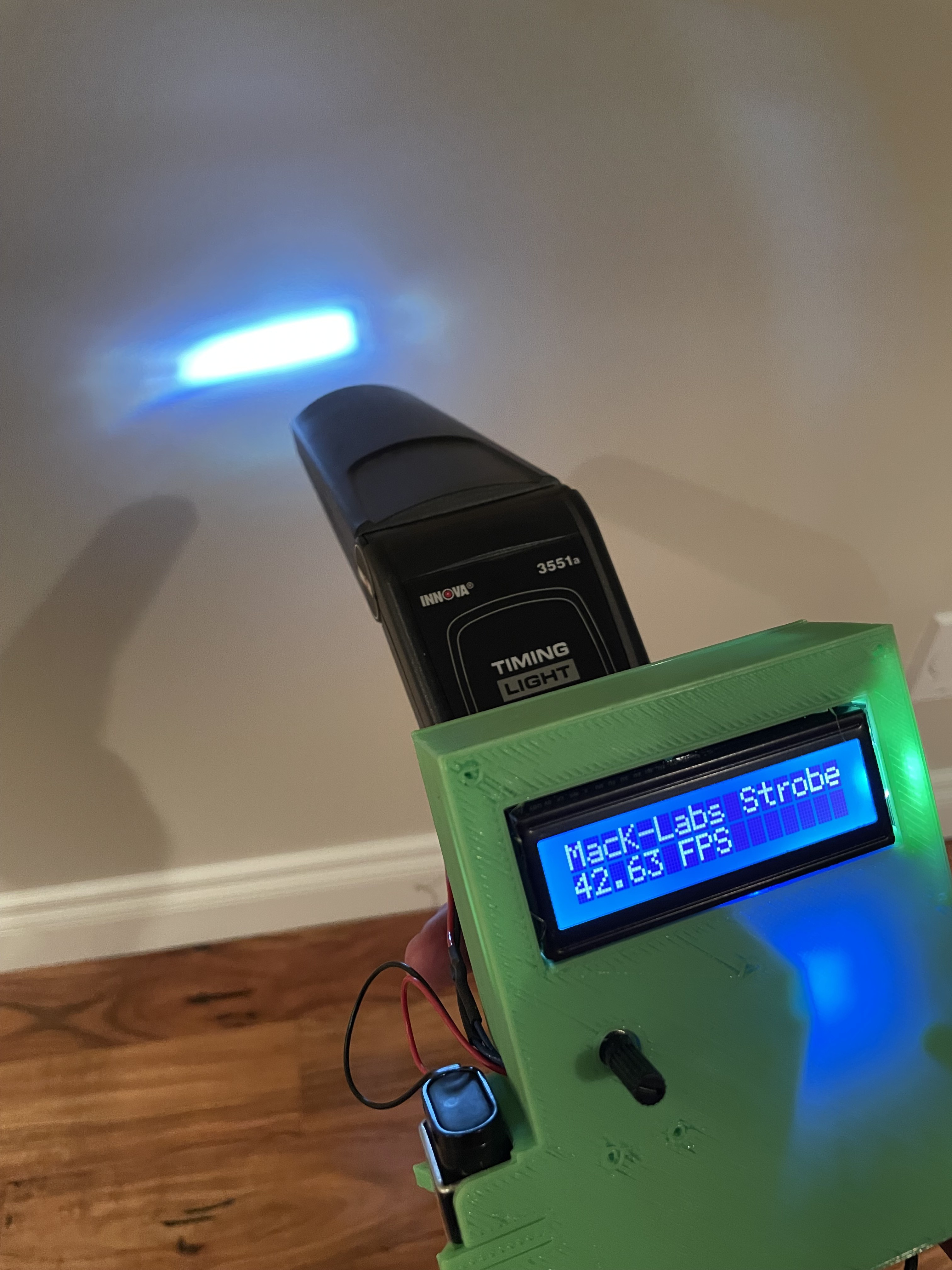
As the generators oscillate very quickly, whenever one wouldn't work I often couldn't tell what the problem was. For troubleshooting, I built a "stroboscope" by hacking into an automotive timing light and adjusting the strobe timing with an arduino. With my stroboscope, I could turn out the lights, and adjust the frequency of the strobe light to be close to the oscillating frequency of the FLAG. This would create the optical illusion of the FLAG moving in slow motion to help me troubleshoot it. The light beam was a little too narrow to make the illusion perfect, but it was good enough to be helpful.
![]()
The slow-motion on the newer iPhone models has become so good, the stroboscope was quickly retired.
Flexible circuit wind generator
A new way to generate wind energy using only polyester film based flexible circuits