OMNi’s power comes from a CBL14-12 battery (12V 14Ah) with all components protected by a fuse block. The second platform of OMNi houses the electrical subsystem and unlike the other platforms is laser cut from black acrylic to avoid short circuits when mounting electrical components directly to the surface.
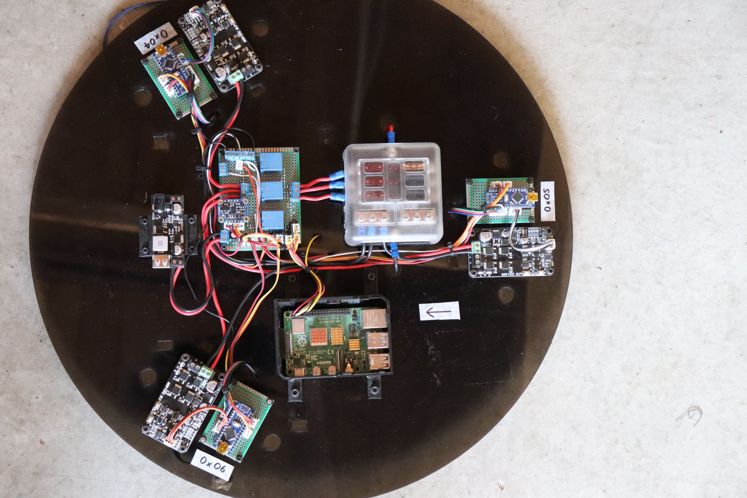
The picture above shows the electrical layout with a 12V to 5V black voltage regulator in the center-left. Next to it is a circuit assembly that houses a BNO055 inertial measurement unit and 3 relays that carry power to each of the 3 motors via 3 separate MD10C motor drivers. Also in the center of the black acrylic platform is a 6-blade fuse box and the computer, a Raspberry Pi 4. Finally, there are 3 Arduino Nano boards around the circumference of the electrical platform.
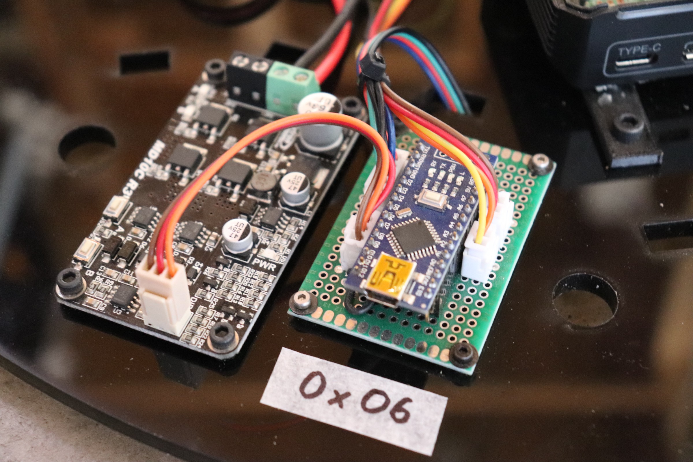
Using a 3.3-volt I2C bus (Inter-Integrated Circuit) the Raspberry Pi 4 communicates with the Arduino Nano boards, each with its own unique address (the Arduino in the picture below has an address of 0x06). Each Arduino Nano uses an interrupt service routine to measure the RPM of its respective motor and controls the speed using a closed-loop PID controller (proportional integral derivative).
In the event, the robot needs to be stopped immediately there is an emergency stop button (normally closed) that when pressed cuts power to a set of relays (shown below), and thereby cuts power to the motors. This setup ensures the motors can be stopped immediately but it does not cut power to the Raspberry Pi, this is a useful design feature both while developing the robot as well as when it is deployed as it allows continued data logging of the event for later analysis if required.
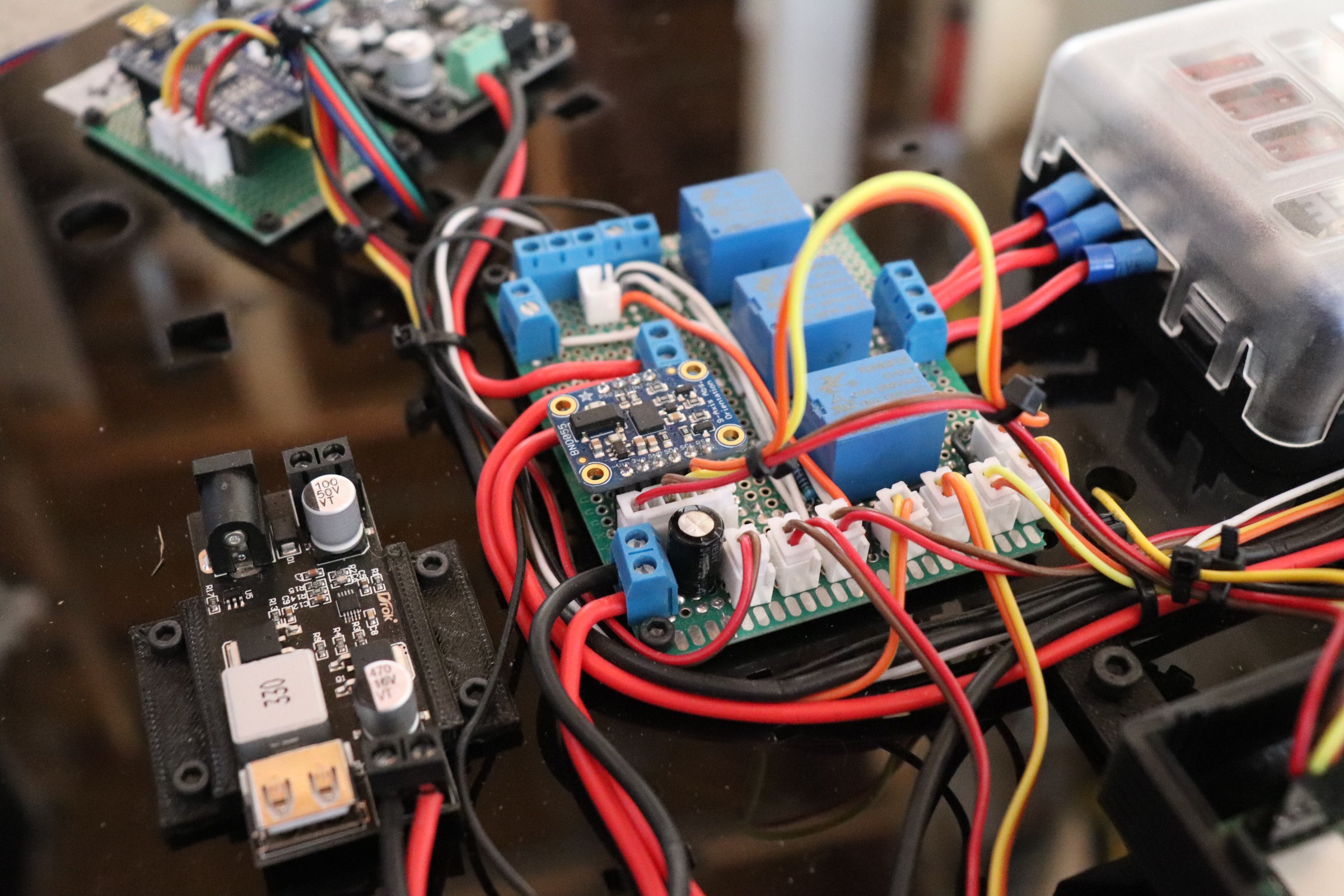
Also in the picture above is a BNO055 IMU (inertial measurement unit). While more expensive than many other IMUs, the BNO055 was chosen as it calculates accurate orientation readings using sensor fusion algorithms on a high-speed ARM Cortex-M0 based processor. This small investment thereby significantly decreases the difficultly in programming and calibrating the robot as well as marginally reducing the computation load.
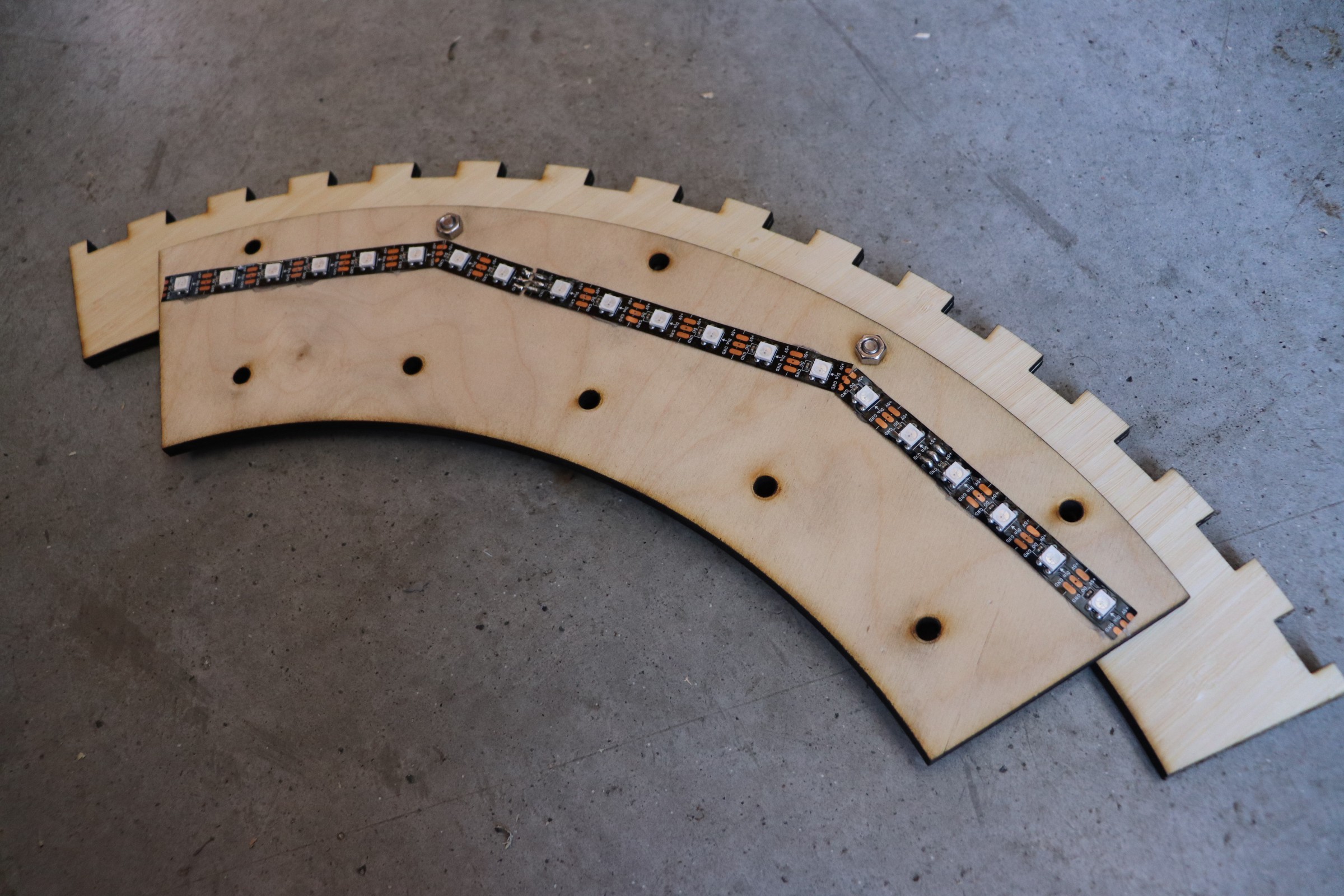
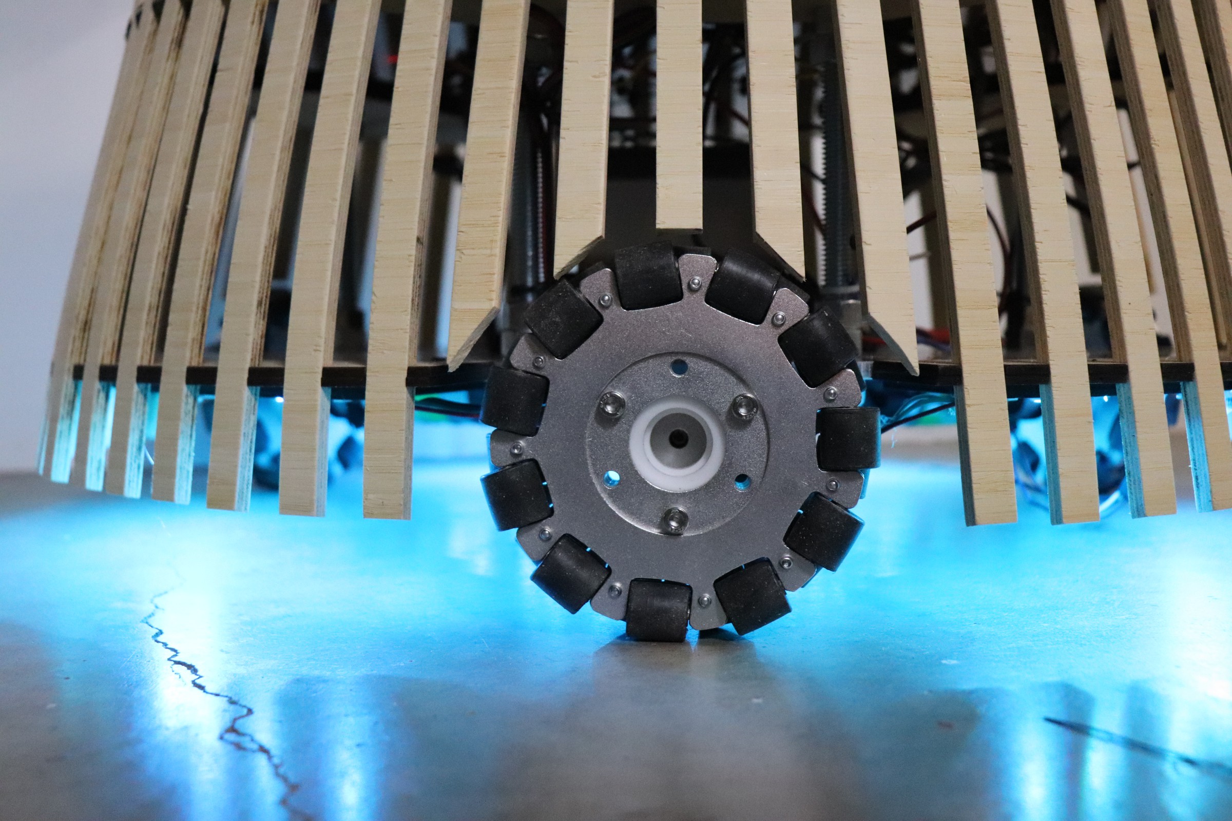
Underneath the robot, a ring of 60 RGB neopixels is attached, in addition to adding an aesthetic ambient light to the robot, these neopixels communicate information to people in the local vicinity. For example, in the future, the lights may gently pulsate while charging before turning a solid color when fully charged, alternatively the lights may turn red when the robot encounters an unexpected event or environment as a warning or error code.
Generally speaking, the sensor modules that can be attached to the robot (LiDAR, camera, robotic arm, tablet) and all self-contained subsystems and interface with the main electrical system via USB serial communication.
 Will Donaldson
Discussions
Become a Hackaday.io Member
Create an account to leave a comment. Already have an account? Log In.