Since I do not have the skills to design boards, I created the circuit using universal PCB boards.
Although four PCBs are used, all of them are just for connecting devices, so you can use them without boards and just connect cables to each other.
Here is a table showing the connections for each.
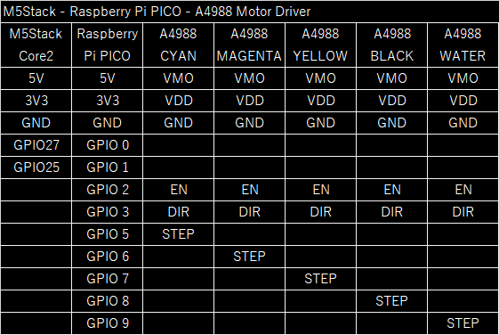
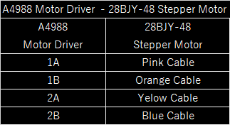
The resulting board is as follows:
1.M5Stack connect board
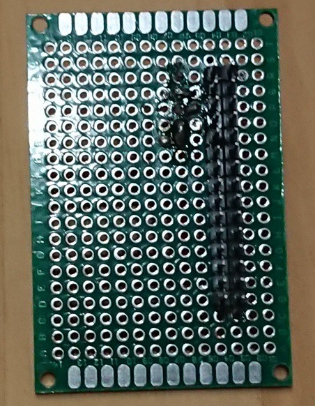
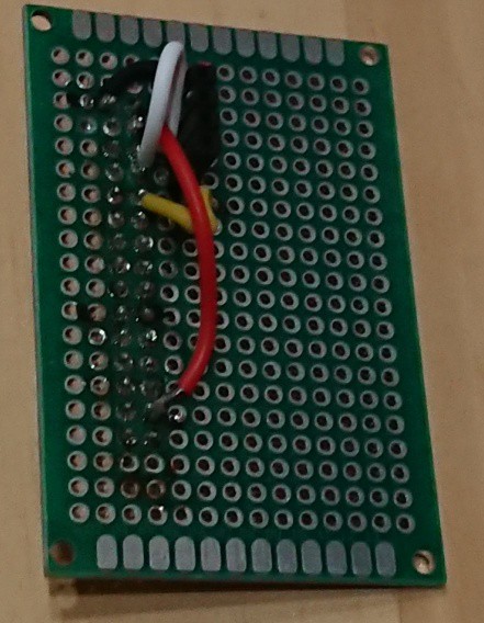
2.Raspberry Pi PICO connect board
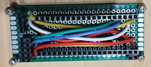
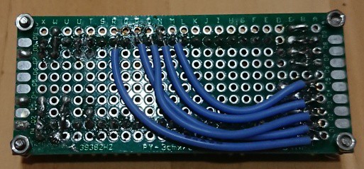
3.Motor Driver & Stepper Motor connect board
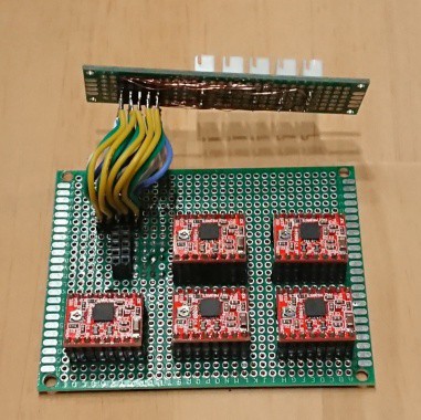
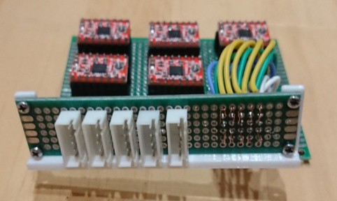
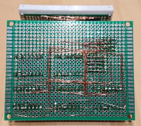
I used AWG24 cable or 0.1mm UEW cable for the connections in the boards, as UEW cable does not take up much space and does not need to be removed, so it is very easy to wire once you get used to it.
 AIRPOCKET
Discussions
Become a Hackaday.io Member
Create an account to leave a comment. Already have an account? Log In.