Goals
The laser timing gate is a simple stopwatch that is triggered optically for lap timing. It should be
- eye safe
- usable indoors or outdoors
- be accurate to 0.01s
- mountable on a tripod
- battery powered
- can be started by the athlete or a starting trigger
- have physical controls and a display
- have remote controls via a phone app or browser
As an extension, it would be nice to be able to pair two gates together to time one-way events, and integrate the light source & receiver in the same unit (only one tripod required per gate).
Scenarios
Athlete Initiated Starts
When an athlete initiates the start, the timing gate starts in an idle state when the beam is aligned on the photo sensor. When an athlete steps into the starting area and breaks the beam, the gate is ready. A starter/official can then arm the gate. The athlete can now start when ready. When the athlete moves and the beam reconnects, the timer starts. When the beam is broken again, the time stops and the lap is finished.
Design
The initial design is based around an ESP32, which in addition to providing the simple physical interface (buttons, LEDs, small display over I2C) can also provide a wireless connection over WiFi or Bluetooth. The onboard ADC is used to monitor the illumination level on a photoresistor, and a threshold determines if the light is at the "beam" or "ambient" level. Interrupts are used for timing. Two LEDs indicate status, and an onboard display will indicate the state of the gate and show the stopwatch time during a lap.
Interfaces
I thought I'd write up some detail in this section since this is where most of the interesting design choices came up (both in hardware and software).
Status LEDs
Two LEDs indicate status.
- a red LED shows if the beam is attached or broken (on=attached)
- a green/blue LED shows that the gate is armed and that the next action (beam connection changes state) will start the timer
These of course also serve as basic diagnostics and can be repurposed to show e.g. network status.
OLED Display
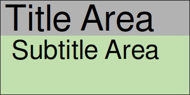
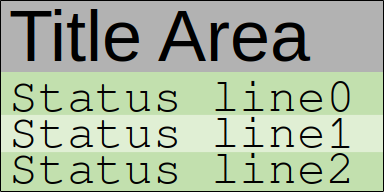
The OLED display is used to show the status of the stopwatch (e.g. Idle, Ready, the running time & lap time, etc.) and other configuration status. Visually it is divided into two sections: a title line (about 10 characters) occupying the upper third of the display, and either a subtitle line or up to 3 status lines in the lower two thirds.


A third option (for the stopwatch time) centers the title area vertically. The DisplayManager class encapsulates this interface, and is composed of GFXcanvas1 and Adafruit_SSD1306 objects (thanks Adafruit!). With more time here, I'm sure a much nicer UI could be implemented, but the idea is to put that effort into the browser interface.
Navigation Buttons & Onboard Menu
I was aiming for a minimal interface for navigation, so there are two navigation buttons: "next" and "apply". This is similar to some interfaces on monitors. I eliminated the "back" action by adding that as a soft option in each menu, and similarly re-used the "apply" button to accomplish an "in" action. This works for small menu systems. The idea is that more complex interactions can be achieved through a remote interface.
The onboard menu only needs to include three categories: the stopwatch, light sensor calibration, and basic wireless configuration (i.e. enough to provide a remote interface). This also ensures that there is enough control through the onboard interface to operate the timing gate without the remote interface as a fallback. There is a state tree in the readme for more information.
Web Interface
To make the interface more accessible, the unit also provides a simple web front end. The ESP32 starts in AP mode. A connection to that WiFi network (currently hardcoded SSID & password, no connection to an external network) provides access to the web server on 192.168.1.1, which hosts a simple status page. The time status (ready, set, go) and running time are then displayed. Messages are passed from the physical unit (host)...
Read more » xdylanm