The CV16 is probably the most complicated module in this project since it is supposed to be fairly flexible. The plan is to use core 1 for time-sensitive tasks like driving the led-matrix and outputs. While core 0 takes care of the MIDI processing, menu system, and anything else. The focus so far has been to restore old functionality and get the DAC working.
My soldering was pretty shoddy this time, I had some short-circuits which led to the opamps and mux reaching 70C. They still reach the low 40s after fixing the shorts. It is better, but still a bit spicy.
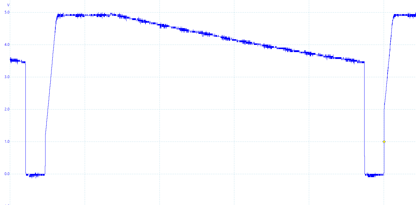
I made a couple of blunders when I re-designed this module. One SPI bus is busy just servicing the DAC, but the EEPROM is also connected to this bus. So those connections need to be changed. The DAC load is purely capacitive which leads to the initial current being high (likely higher than the max rating of the MUX) and causes ringing. I'm guessing this also contributes to the high temperature in these components.
All the old code has been ported to the RP2040 now, I also started refactoring and optimizing some of it. The refresh rate on the LED matrix has been increased to 60Hz, and the module output rate has been increased as well. Otherwise, the only feature I have added is key-tracking oscillators, which means this module can generate sound directly.

At first, the output voltages were only correct when the neighboring voltages were the same, and spikes could be seen when the MUX switched. Turns out the DAC settling time was longer than I expected. The DAC settling time from the LDAC edge is 7µs when the voltage change is 5V, which is longer than the multiplexing hold period at 44kHz (5.6µs). The settling time would be 5µs if the voltage range was halved, but doing that would increase the circuit complexity. Currently, the output rate is reduced to 22kHz to get around this, but the neighboring outputs were still affecting each other.

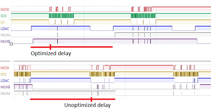
It finally turned out the timing issues were caused by a massive delay when writing values to the SPI. To reduce this delay I switched to PIO so it can handle the CS pin instead of software. I removed some division and modulo operations because they eat many CPU cycles. Then, set core1 as high priority on the bus fabric and used a setting to have these functions loaded in the RAM instead of flash to further reduce the delay. This resulted in a healthy margin between the end of writing and LDAC.

There is still some noise when switching, but since the sample rate is above 20kHz it is less of an issue. The noise is not noticeable when the outputs are used to modulate pitch, and they can even be used directly as a DCO. It has some nice aliasing on the upper range of frequencies which can be heard at the end of this video:
Making changes leads to lots of troubleshooting, but I believe most hardware changes on all modules have been troubleshot now. I will order a new revision of this main board, mostly to move the EEPROM to the other SPI bus. The EEPROM is working on the tangle module so I'm fairly confident it won't cause more issues.
There is still more to do on this module, I'm going to finish refactoring the output handler and menu system. More waveshapes will be added like multiple kinds of noise, pulse waves, and maybe even supersaw. I also need to figure out how to organize the configurations in the EEPROM.
 David
David
Discussions
Become a Hackaday.io Member
Create an account to leave a comment. Already have an account? Log In.