David
David-
Bus protocol
10/14/2021 at 00:36 • 0 commentsDeciding how the bus should behave is a bit easier as it can be adjusted afterward. The simplest solution is to use the CAN frame as a wrapper for the MIDI message. I did think about using one or two bits of the ID to define special messages, but it seems unnecessary.
The CAN ID could contain some info about the MIDI message like type, or channel. That way some modules can filter out messages in the CAN controller, which means the CPU will see fewer interruptions. However, as far as I've understood the CAN bus it only uses the message header for arbitration. So, using the ID field like this will lead to more collisions and a reduced bandwidth. It may be better to use randomly generated IDs, so that each module on the bus has a unique ID. This would probably require a mechanism to detect address collisions to generate a new ID.
One thing I'm unsure about is the 7-bit sysex messages. The specification says no messages should be interleaved with the sysex message. We could reserve CAN ID 0 for these messages so they always win arbitration, but that assumes we only have one sysex transmitter. But we can also use the CAN ID to determine which device sent the message, to reconstruct the sysex.
-
Defining the bus
10/13/2021 at 23:41 • 0 commentsSo, I had to decide which communication bus, connectors, and cables to use. Here I try to explain my thoughts, and why these choices were made. Some of my choices are likely a bit naive or not properly thought through, but I also feel like I'm overthinking things. So, some feedback would be appreciated.
The bus should have half-duplex communication, allowing modules to answer messages from other modules. But most messages will be broadcasts without requiring an answer. Preferably, the bus should not need an arbiter to control the communication. That way any combination of modules will work together. It would be great if the bus datarate was comparable to USB 2.0, but there is no hard requirement. MIDI 1.0 has been in use for several decades, and its datarate was 31.25kbit/s.
I did consider some other choices before deciding to go with CAN, like staying with I2C. Which is cheap to implement since most modern MCUs have it integrated. But it will limit the length and speed of the bus because of its lack of robustness. One way to improve robustness is differential I2C, but it isn't used as much so the choice of transceivers is limited.
Another possibility was to use UART over RS-485. However, this does not have built-in arbitration or collision detection. Since RS-485 transceivers are push-pull a collision would result in high short-circuit currents, which is not ideal. So RS-485 does not make sense in a multi-master system.
M-LVDS has similar problems as RS-485, only with lower short-circuit currents. But it will likely have the lowest EMR of all these choices during normal operation, due to the low voltage swings. Whether electromagnetic radiation is a problem in this project remains to be seen.
And finally the CAN bus. This is a bit more complex than the other choices, it may need an external CAN controller depending on the MCU. But it handles arbitration, collision detection, and even re-transmission automatically. Which means writing the driver will be simpler. One limitation of CAN 2.0 is the maximum payload size of 8 bytes, while MIDI 2.0 can have messages up to 16 bytes. Here we have two choices: re-construct the messages afterward, or use CAN-FD which has a maximum payload of 64 bytes.
I decided to go for CAN-FD because it seemed like the least amount of hassle to implement. Since many of the issues with multi-point communication are already handled. It can achieve datarates of 1Mbit/s with the possibility of increasing it. This should be enough for a decent sized system.
Twisted pair cables look like the most natural choice for a CAN bus, but it needs a way to connect many short cables. The space in eurorack enclosures can be limited, so the solution shouldn't be too bulky either. One way is daisy-chaining connectors, which can be really awkward to assemble and leaves little room for changing module placement. Another way is using T-connections, which requires more space in the enclosure. Or having two connectors on every module, which I did on the previous iteration of this concept.
Flat ribbon cables are most convenient, as it's just one cable where connectors are added as needed. They are known to be good antennas though, so the system may be more susceptible to electromagnetic forces. However, this being just one cable leads to short stubs and low signal skew on the bus, which helps with EMR.
This time I decided to try ribbon cables for convenience. It seems like the best practice for differential signals in ribbon cables is to have the pair close, and surround it with ground (gnd s+ s- gnd). The idea with ground on the edges is providing a return path for any radiated current, and to prevent ground loops a high-pass RC filter is used on the PCB.
The connectors should be non-reversible, so they can't be inserted the wrong way (unlike the eurorack power connectors). Connectors being distinct in eurorack would be a plus, so no unshrouded pin-headers with 2.54mm pitch. However, the connector must be readily available, preferrably from more than one manufacturer. Connector assemblies should also be DIY friendly, that is not requiring special tools. Thus, IDC connectors would be ideal as they can be assembled with common pliers.
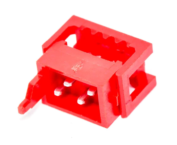
Many applications of the CAN bus uses 9-pin D-sub connectors, but these are quite large. I ended up using these red connectors with staggered pins, which fulfill all the requirements. TE-connectivity calls them the Micro-MaTch series, while Wurth Elektronik uses WR-MM series.
End termination can be external connected to cable ends (like a tiny dedicated PCB). Or it can exist on every module, where a DPST switch or jumpers could enable it. Split termination would be preferred as it stabilizes common-mode voltage on the bus, and reduces radiated emissions (Ref). This is not compatible with the external end termination method, because it requires a solid ground connection. So the only choice becomes having the end-termination circuit on every module.
-
The motivation
10/12/2021 at 18:01 • 0 commentsThis is technically a continuation of an earlier project I did. There I used an I2C connection to send MIDI messages between eurorack modules. This does work with low frequencies over short distances. However, I2C is not exactly known for its robustness. Also, the MIDI 2.0 specification was made public during the development of those first modules. So I wanted to make those modules more future-proof.
MIDI in eurorack is usually only used to generate control voltages. And I think more digital control in eurorack could be cool. Being able to recall settings and patches using program change messages would definetively be useful in a performance setting. Remapping the functions of knobs would be possible, they don't even need to be on the module they're controlling. And with the improved resolution of MIDI 2.0 a controller knob can be indistinguishable from an analog knob. This will probably end up being a niche within a niche, but I believe having more options is positive.
The main purpose of this project is to integrate MIDI 2.0 in eurorack. Currently the only transport for MIDI 2.0 is USB, but having USB on many modules can be inconvenient both for developers and end-user. For users this simply means several USB cables and hubs. For devs the USB stack may provide a lot of overhead in simple applications. Also, the modular synth community has a lot of small manufacturers, and hobbyists. So the USB licensing may prevent this part of the community from taking advantage of MIDI 2.0.
Therefore I think defining a new transport for MIDI would be useful for eurorack and other modular systems. And to this end a multi-point bus would work great with MIDI, since most messages should be broadcast to every other module on the bus.
The prototype to demonstrate this transport will be four modules: A DIN-5 gateway for the old MIDI 1.0 transport, a control voltage module to interact with the analog modules, a multiplexer module to change patches with MIDI, and a USB gateway for MIDI 2.0.
Modular MIDI
Using a CAN bus to distribute MIDI messages in a modular synthesizer