 AberDerBart
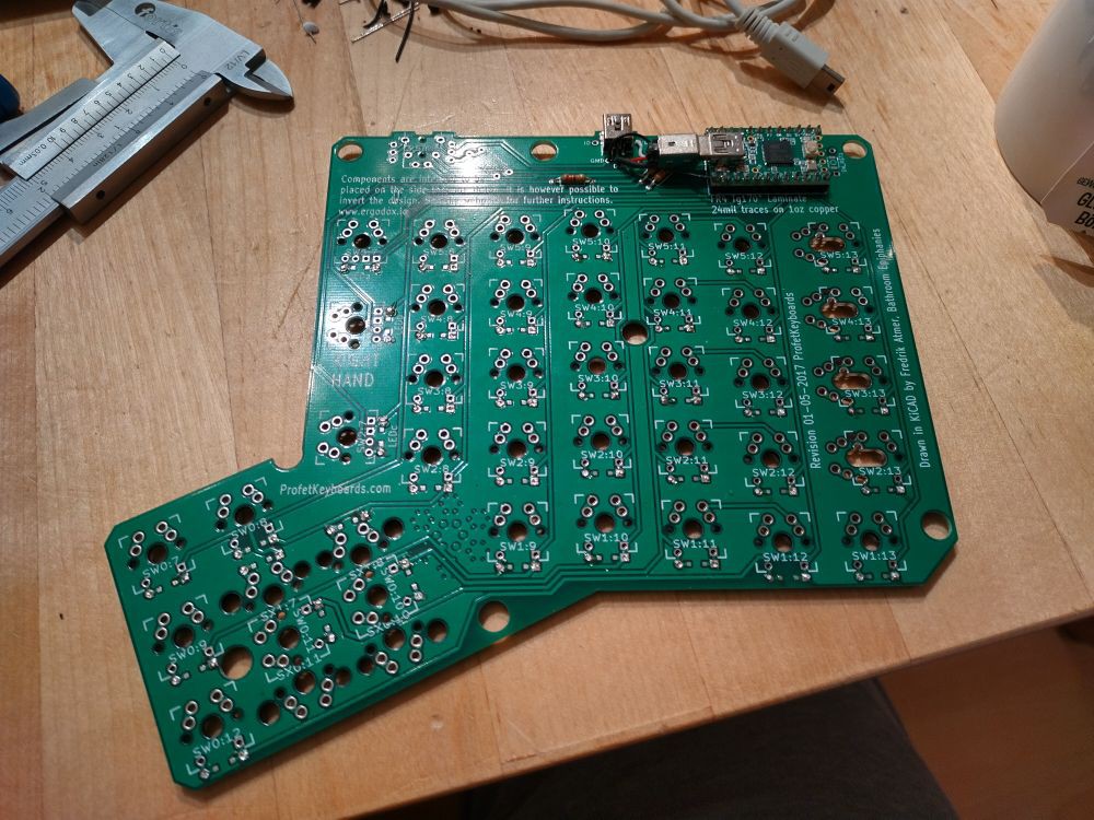
The only fiddly thing is soldering the mini usb cable (I cut one wire by accident when removing the insulation, fortunately it was the ground wire, so I could just solder it to the ground pin of the Teensy).
This is one thing that always irritates me when using microcontroller dev boards with usb support - why aren't the usb data pins exposed on the PCB? Often there are test points, but a through-hole pin would be so much easier...
If I do a second iteration on this, maybe I'll adjust the board for the RP2040 soldered directly onto the PCB - this would be much cheaper (after all, a Teensy 2.0 costs about 20€) and more compact.
The case did not match perfectly, the recess for the Teensy is a little bit too small. As the upper half of the case will be connected to the PCB by the key switches sitting in it, I am considering to redesign it to be split in two parts, so I can replace the outer part for cosmetic changes.
Discussions
Become a Hackaday.io Member
Create an account to leave a comment. Already have an account? Log In.