So basically I'm terrible at designing housings for my electronic creations - things change mid project, the housing ends up being sub-optimal to outright disruptive - check out my FrankenFlight controller to see an example.
So this time round I decided to go the whole hog with Fusion 360 and mock it up in its virtual entirety. The 1st pic in the gallery is an indication of this. Leave NO stone unturned in your pursuit of modelling everything to reveal any fitment issues prior to 3d printing - and I think it paid off this time!
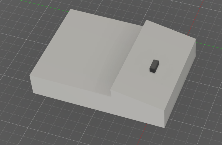
This is the heating controller body, bits of importance only - the black oblong is the boost button as measured - this is all from actual measurements.
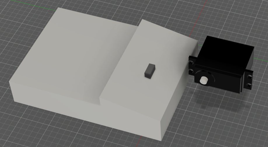
This is the servo positioned accordingly to line up with the boost button -
Now the other bits are put in place, while positioning them I thought about wall clearance distances too.
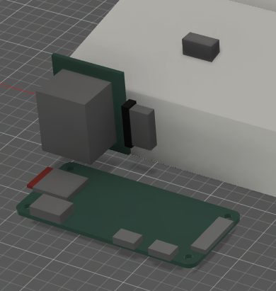
This is the Raspberry Pi, as lifted from their own specs PDF sheet, really handy!
The board on the top left is the MOSFET breakout board (see future project log for details on this). This is to scale, but I've only boxed out the areas, the big block in the middle is just the protruding MOSFET package, very roughly scaled up to help avoid any interference.
I use different design files for each component, then create a main design project drawing and bring them in by just dragging them in from the project drawer on the left. This has the advantage that you can open the original drawing again, make changes, then update them on the main design drawing.
I position them roughly as required and adjust to fit.
After that I just box up the whole case around these components, also putting mounting points in place for the bits. For this I see zero reason to make it a design masterpiece, even a black oblong can be suitable and pretty attractive for something like this - didn't even use the bevel / fillet tool once!
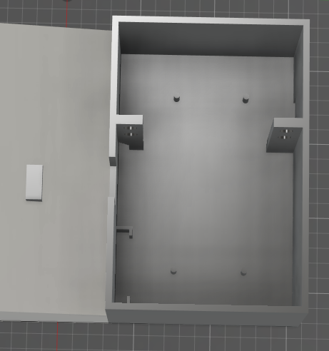
And here's the lid -
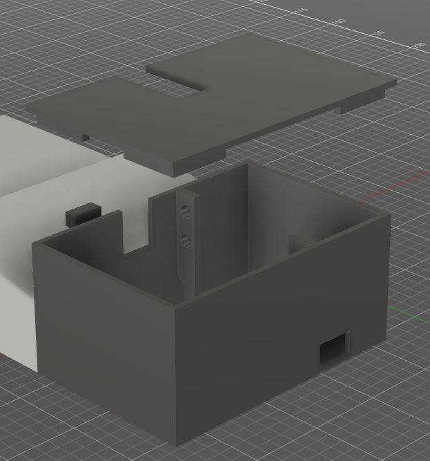
Here you can see the slot for the USB cable to power the Pi, servo and everything - leave no stone unturned!
And this is everything in place -

It really helps to have done a lot of 3D printing as I have, and learned the various challenges printing such a model. Things to consider -
- Can the printer print overhangs effectively, how long an overhang can it manage? 3D printers do not (successfully) print in mid-air!
- Post and hole dimensioning so they come out correctly the right size (holes tend to shrink due to plastic shrinkage and posts are really awkward, can easily be done too wide, with lots of stringing with the wrong temps and retraction settings. Aim to model gaps of 0.3mm to 0.5mm to your objects.
- At all stages think about the model orientation as it'll be printed - that way you'll know about all the overhangs, and obviously the case lid / siding without violating the laws of gravity. I've printed the case base down as normal, have modelled the lid to be printed upside down, with lips guiding the lid into perfect position.
I think I've come on leaps and bounds at project housing design - here's a sneak peak at the end result (sans actuator arm, because I've not made it yet).
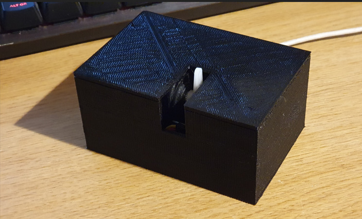
Yes I've left the lid on for now - saving the 'reveal' for later! I'm not exactly done yet tho - still need to -
- Build an actuator arm with spring loaded tip - currently just shown with a servo horn.
- Develop the software stack to make it work (currently SSHing into it to make it move)
- Find a way to securely attach this to the side of the heating timeswitch - this means figuring out a way to stop it 'flexing' when pressing the button, ensuring it doesn't just push itself away having not enough 'heft' to press the button fully - yes this is something I missed out in the design stages, but it's a different challenge. I might just attach it with a strapping or something, just some thick string or some strong tape.
- fine tune the motion of the arm to prevent long-term button damage.
- etc.
- Dig a little deeper into integration with Alexa (I've actually done this before but the open software to do it was a bit janky at the time).
Discussions
Become a Hackaday.io Member
Create an account to leave a comment. Already have an account? Log In.