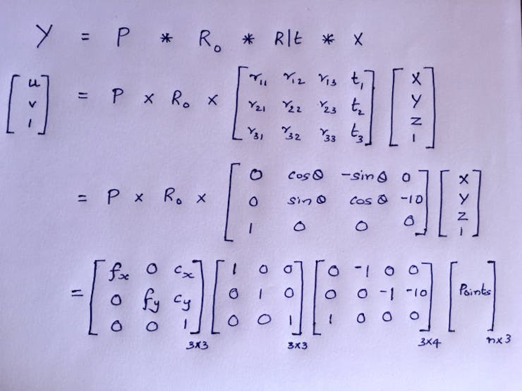
To do LIDAR-Camera Sensor fusion, we need to do rotation, translation, stereo rectification, and intrinsic calibration to project LIDAR points on the image. We will try to apply the fusion formula based on the custom gadget that we built.
From the physical assembly, I have estimated the Pi Cam is 10 mm below the LIDAR scan plane. i.e. a translation of [0, -10, 0] along the 3D-axis. Consider Velodyne HDL-64E as our 3D LIDAR, which requires 180° rotation to align the coordinate system with Pi Cam. We can compute the R|t matrix now.
As we use a monocular camera here, the stereo rectification matrix will be an identity matrix. We can make the intrinsic calibration matrix based on the hardware spec of Pi Cam V2.

For the RaspberryPi V2 camera,
- Focal Length = 3.04 mm
- Focal Length Pixels = focal length * sx, where sx = real world to pixels ratio
- Focal Length * sx = 3.04mm * (1/ 0.00112 mm per px) = 2714.3 px
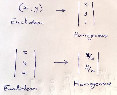
Due to a mismatch in shape, the matrices cannot be multiplied. To make it work, we need to transition from Euclidean to Homogeneous coordinates by adding 0's and 1's as the last row or column. After doing the multiplication we need to convert back to Homogeneous coordinates.

You can see the 3DLIDAR-CAM sensor fusion projection output after applying the projection formula on the 3D point cloud. The input sensor data from 360° Velodyne HDL-64E and camera is downloaded [9] and fed in.

However, the 3D LiDAR cost is a barrier to building a cheap solution. We can instead use cheap 2D LiDAR with necessary tweaks, as it only scans a single horizontal line.
 Anand Uthaman
Discussions
Become a Hackaday.io Member
Create an account to leave a comment. Already have an account? Log In.