Pendulum Body
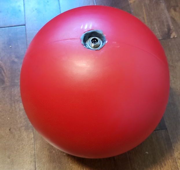
The IMU board is built into the pendulum body. The pendulum body is a 10-inch plastic ball. Since the IMU uses wireless communication to transmit data to the host, it only needs VCC and GND lines to operate. I used a GX-16 4 pin connector on the top of the pendulum and epoxied the connector inside a ball bearing to give it rotation freedom. The 4 pin connector is connected to a slip ring whose other side is connected to the IMU board. For now, I am using STM32F411CE (AKA BlackPill) to handle the processing but may migrate to Teensy 4.0 at some point.
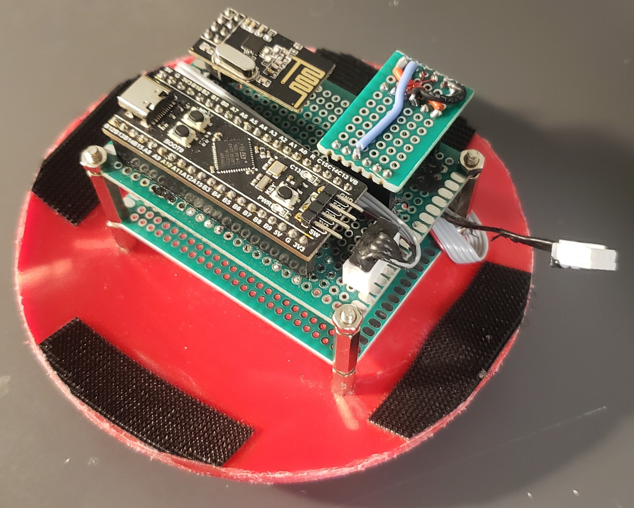
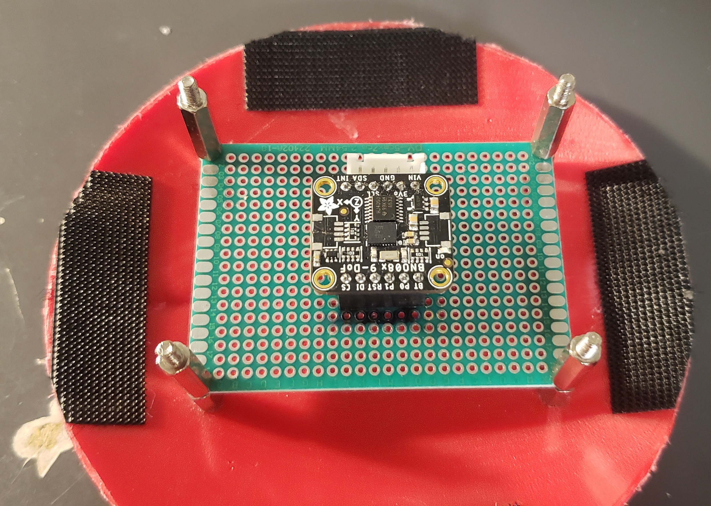
IMU board
The IMU board houses the main processor board (BlackPill), the NRF module and the IMU sensor (BNO085). The IMU sensor is moved to a new board under the rest of the components. This is because the IMU sensor must be at the lowest point and the centre of the pendulum to work optimally. As mentioned, the IMU board is connected to a slip ring which is connected to a 4-pin GX16 connector. The 4-pin connector is connected directly to the USB port of the BlackPill, caring power and serial data for debug purposes.
Host/ Master Device
The host uses a Teensy 4.0 to process the input data received form the NRF network, process user input and UI. The three potentiometers control the intensity of each axis or the constant values used for some of the modes.
Modes
There are 5 modes of output that are currently active:
- Gravity: outputs continues motion of the pendulum as MIDI control signal and CV voltage
- Gravity+: outputs continues motion of the pendulum only in + direction (absolute value of motion) as MIDI control signal and CV voltage
- P2T: peek to trough, this mode will output trigger signals to MIDI and CV. It triggers when the pendulum is at the right position set with the three potentiometers for X, Y and Z directions
- P2P: Same as P2T but this mode only triggers once in every swing
- T2T: The reverse of P2P. So basically triggers when pendulum is lower than the set value and stays on for longer
- DIV3: divides each swing of the pendulum into three trigger points: two peaks and one mid point at the lowest position
- DIFF: triggers rapidly based on the change in motion. The change constant is set with the three potentiometers.
Mode change is done by holding the push button down for a short period of time.
Screen
The screen shows the real-time movement of the pendulum in the set axis, the potentiometer values and the splash screen :)


NRF Network
At this moment, the host device only supports one pendulum with a bi-directional NRF network. Therefore, it is possible to just add more IMU boards and track more Pendulums in the future. The data from each IMU is identified using the RF24NetworkHeader object and each pendulum's unique address. For P2T, P2P and T2T modes, a mode change signal is sent to the IMU board to reset, and change the mode of the BNO085 sensor. The host also sends a reset signal to all of the pendulums upon booting so they are all synced with the host's initial settings.
USB MIDI
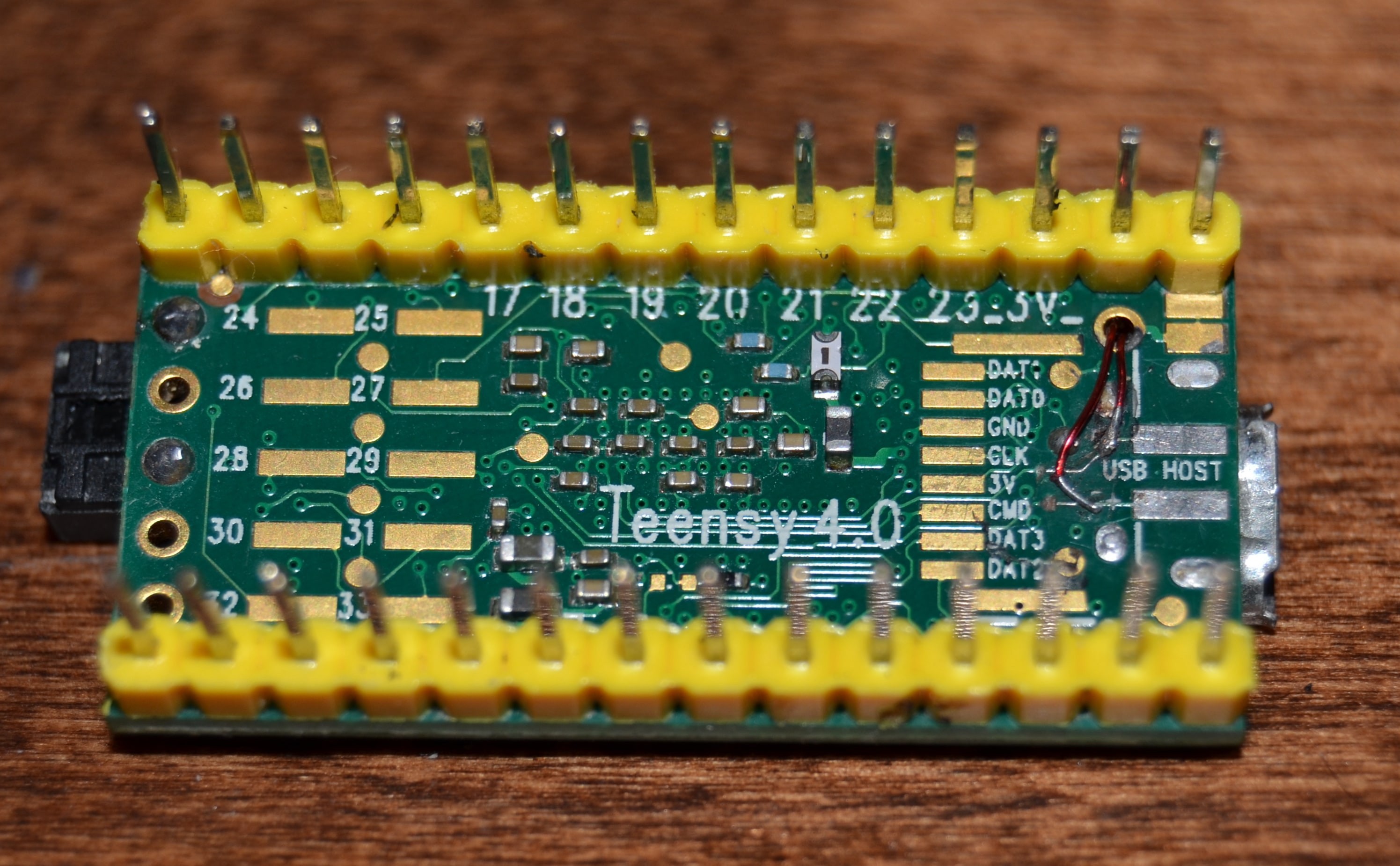
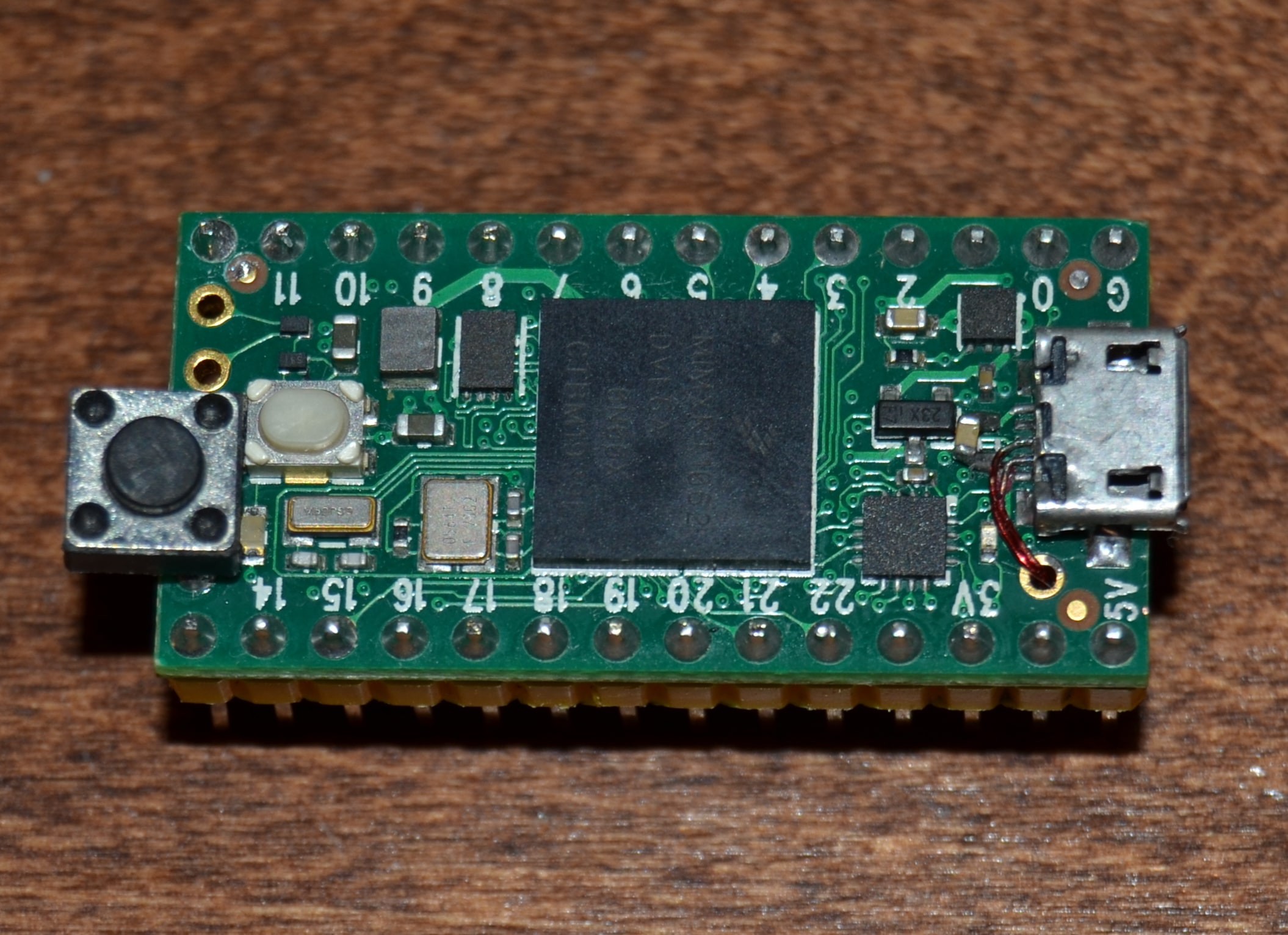
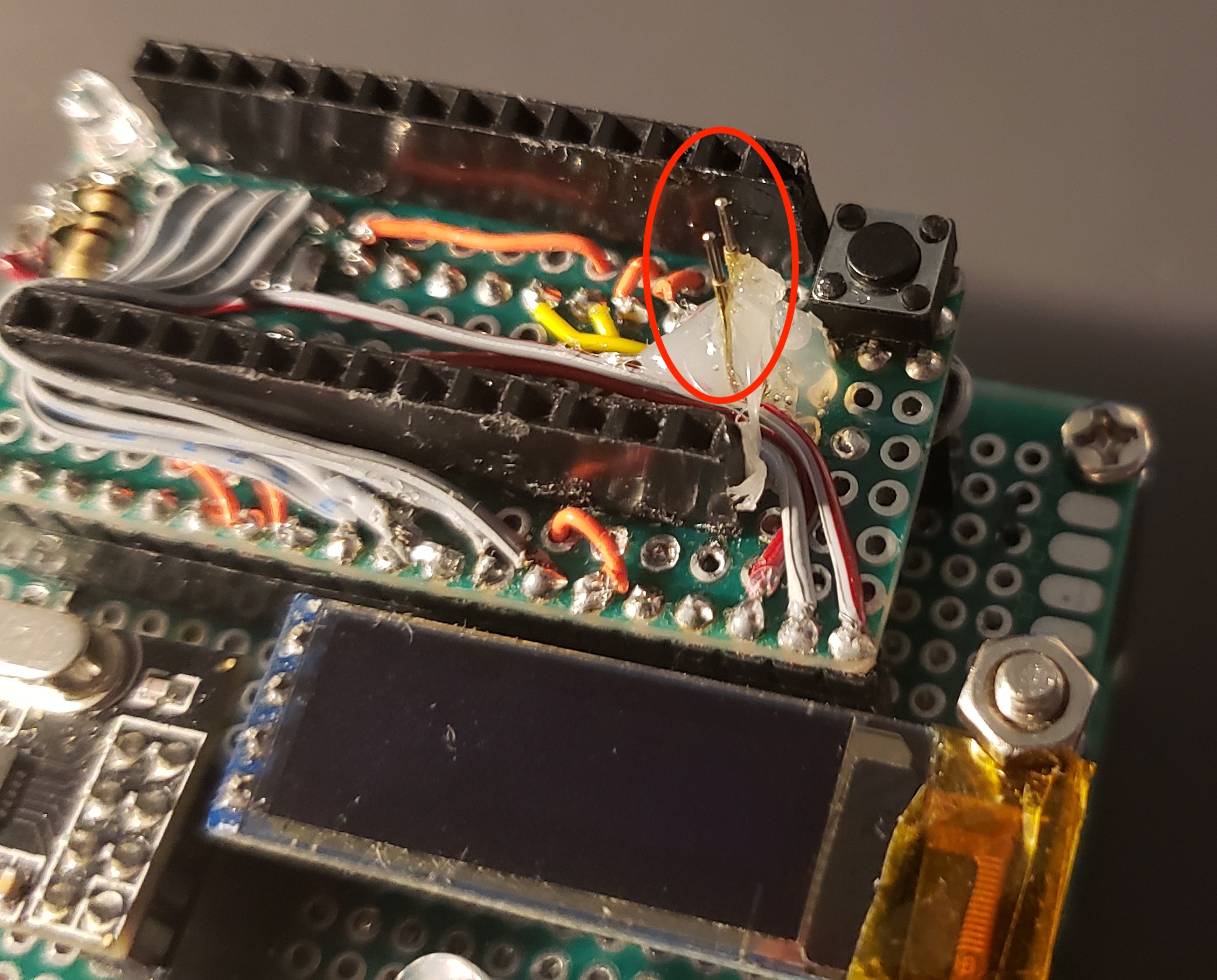
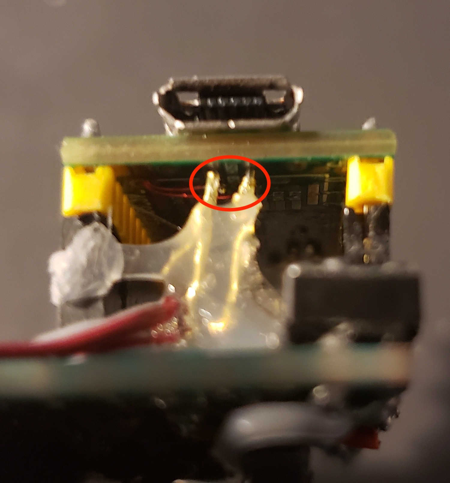
The host device supports USB MIDI alongside with the CV outputs. This was possible thanks to Teensy 4.0 and its amazing MIDI support. However, I had to mod the Teensy to use the USB lines without connecting a physical connector to the Teensy. To rout the USB lines to the back of the device, I soldered two magnet wires on D+ and D- pads behind the USB port and pushed through one of the holes to the bottom side of the Teensy. Then, simply disconnected the USB host pads from their original tracks and soldered the two magnet wires to them. Two pogo pins were used to insure good connection between the pads and the board.
Serial Interface
All of the host's settings could be accessed through USB Serial. You can change the mode, midi channel, midi notes and controls and toggle midi triggers and control signals.
Commands are:
set midi cc MIDI MIDI_CC: sets the midi cc number to MIDI_CC
set midi trig MIDI MIDI_NOTE: sets the midi trigger note number to MIDI_NOTE
set midi channel CHANNEL: sets the midi channel to CHANNEL
set mode MODE: sets the mode of the device and the outputs
toggle midi cc MIDI: toggles the given midi cc
toggle midi trig MIDI: toggles the given midi note
toggle debug: toggles the serial monitor debugger
reset/r: will reset the device
help/h: will show the commands menu
Demo Video
In the following video, I will demonstrate the Gravity, Gravity+ and DIFF modes connected with USB MIDI to Ableton Live.
If you like the project, you can support it or help with the development! Simply clone/fork the repo and commit!