deʃhipu
-
Testing
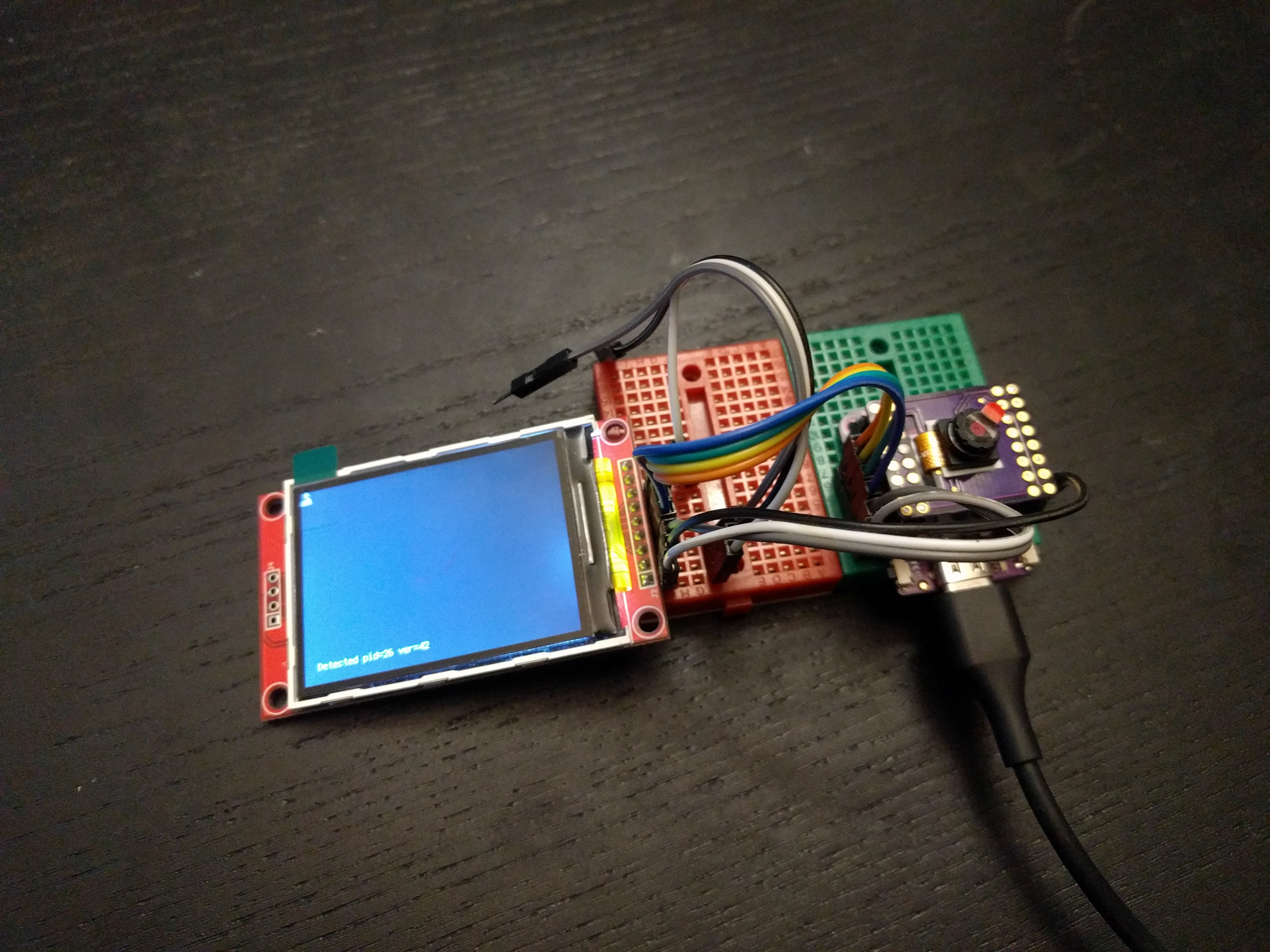
11/27/2021 at 17:54 • 0 commentsThe PCBs finally arrived, but turns out there was a mistake at the fab, and all holes that were supposed to be 0.9mm are 0.6m instead. I managed to solder pin headers to them anyways, so let's do some testing!
![]()
For the test, I decided it would be the easiest to do it with a display. So I wired an ILI9341 to the pins that are not used by the shield, and... it didn't work. Great, displays were supposed to be a solved problem. After some poking around and testing, it turns out that the silkscreen on the Lolin S2 Mini I have is wrong, and it has pins 12 and 13 swapped. After swapping the pins, it works. Great, so now time to try the test code. Based on Adafruit examples, I came up with this:
import board
import terminalio
import displayio
import adafruit_ili9341
import busio
import adafruit_ov2640


displayio.release_displays()
display_bus = displayio.FourWire(
    busio.SPI(clock=board.IO7, MOSI=board.IO5),
    command=board.IO9,
    chip_select=board.IO12,
    reset=board.IO11,
    baudrate=80_000_000,
)
display = adafruit_ili9341.ILI9341(display_bus, width=320, height=240)


i2c = busio.I2C(scl=board.IO39, sda=board.IO40)
cam = adafruit_ov2640.OV2640(
    i2c,
    data_pins=(board.IO21, board.IO17, board.IO16, board.IO18, board.IO33,
               board.IO34, board.IO35, board.IO36),
    clock=board.IO14,
    vsync=board.IO38,
    href=board.IO37,
    mclk=board.IO13,
    mclk_frequency=20_000_000,
    size=adafruit_ov2640.OV2640_SIZE_QVGA,
)

cam.flip_x = False
cam.flip_y = True
pid = cam.product_id
ver = cam.product_version
print(f"Detected pid={pid:x} ver={ver:x}")
# cam.test_pattern = True

g = displayio.Group(scale=1)
bitmap = displayio.Bitmap(320, 240, 65536)
tg = displayio.TileGrid(
    bitmap,
    pixel_shader=displayio.ColorConverter(
        input_colorspace=displayio.Colorspace.BGR565_SWAPPED
    ),
)
g.append(tg)
display.show(g)

display.auto_refresh = False
while True:
    cam.capture(bitmap)
    bitmap.dirty()
    display.refresh(minimum_frames_per_second=0)

cam.deinit()
And... nothing. It seems to hang on the cam.capture(bitmap) line. The good news is that the i2c communication seems to work, as it reports the pid and version correctly. I will need to investigate this further.
-
Pinout
10/29/2021 at 11:17 • 0 commentsJust to make my life a little bit easier in the future, here is the current pinout of the shield:
Pin Signal Note D16 D4 Data D17 D3 Data D18 D5 Data D21 D2 Data D33 D6 Data D34 D7 Data D35 D8 Data D36 D9 Data D37 HS (HREF) Horizontal Sync D38 VSync Vertical Sync D39 SIO_C I2C SCL D40 SIO_D I2C SDA EN RST Reset D14 PCLK Clock D13 MCLK Clock -
Camera in CircuitPython
10/29/2021 at 11:05 • 0 commentsThere is ongoing work being done by Jeff Epler to bring the cameras to CircuitPython. There is an excellent tutorial available here: https://learn.adafruit.com/capturing-camera-images-with-circuitpython
But this is not all. Right now Jeff is working on a way to produce animated GIF images directly from the camera, and save them to the SD card.
There is also a way to stream the video: https://learn.adafruit.com/circuitpython-webcam-with-ov2640
So I'm confident that even if my own software experiments fail, the shield will still prove useful.
-
What is this for?
10/26/2021 at 13:57 • 0 commentsA bit of explanation is needed here. Obviously an ESP32-S2 is not going to be able to do much with a camera, lacking the processing power and memory. I hope to make it stream low-resolution video over WiFi, and maybe, if in the right light conditions, find color blobs at one frame per 10 seconds.
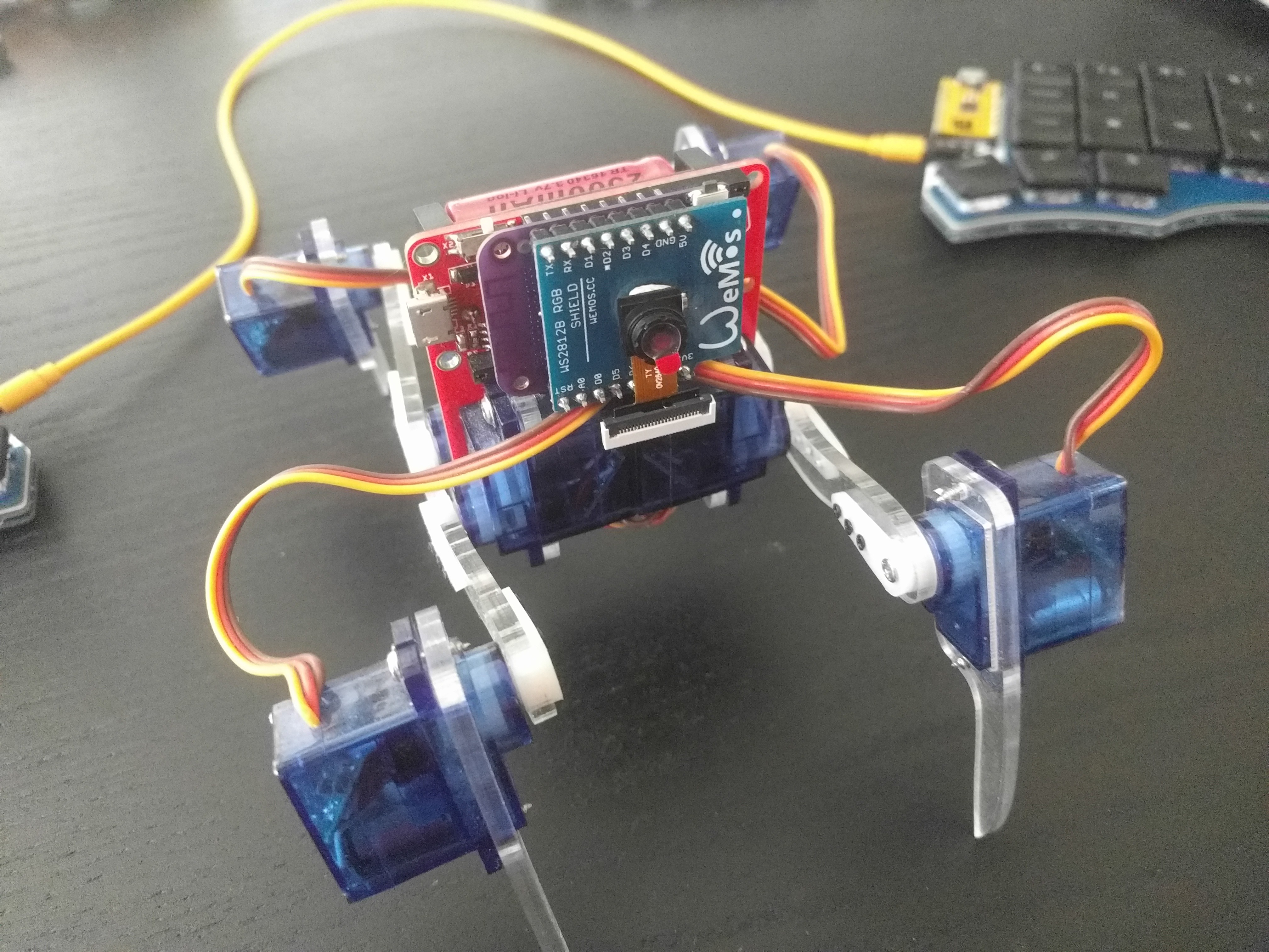
Oh, of course I want to put it on my robot, here's a mockup:
![]()
Since both the robot and the shield are waiting for the PCBs, I used the previous version of the robot and some random shield I had lying around, but you get the idea.
Ideally, if I have a lot of time, and can understand enough of the code, I might be able to port the Apriltags code from OpenMV and use it with the robot — that would be an awesome thing to do, but I doubt if my skills are sufficient.
-
Version 1 PCB
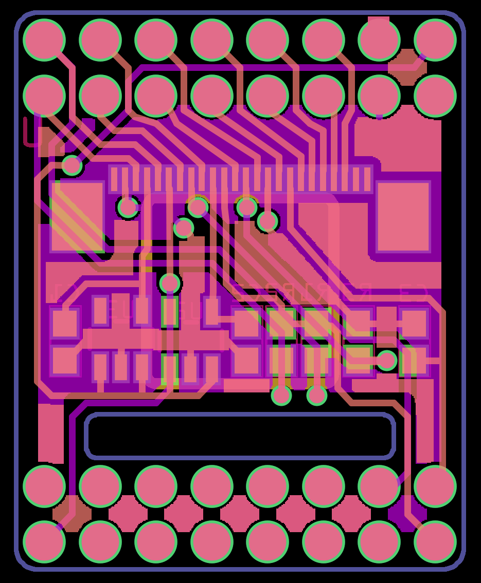
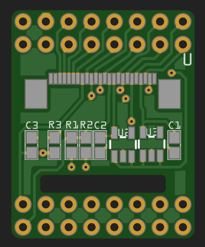
10/25/2021 at 21:34 • 0 commentsThis is the first attempt at this shield, and it's mostly based on guesswork, datasheet, schematic for the ESP32 Cam board, and some bad quality images of the pinouts I found online. I have absolutely no idea if it will work, but I can try. The design is pretty dense:
![]()
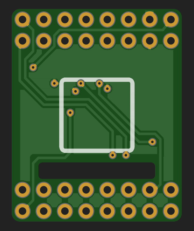
I didn't feel like fixing the angles of all the traces, so you will have to suffer. The render doesn't look bad:
![]()
![]()
There are two voltage regulators, each with its own capacitor, two resistors for I2C pull-ups, a resistor to pull-down the enable pin on the camera, and a 14pF capacitor on the PCLK line, no idea why, but ESP32 Cam had it, so I copied it. And of course the camera socket itself, which is a fun 0.5mm-pitch footprint.