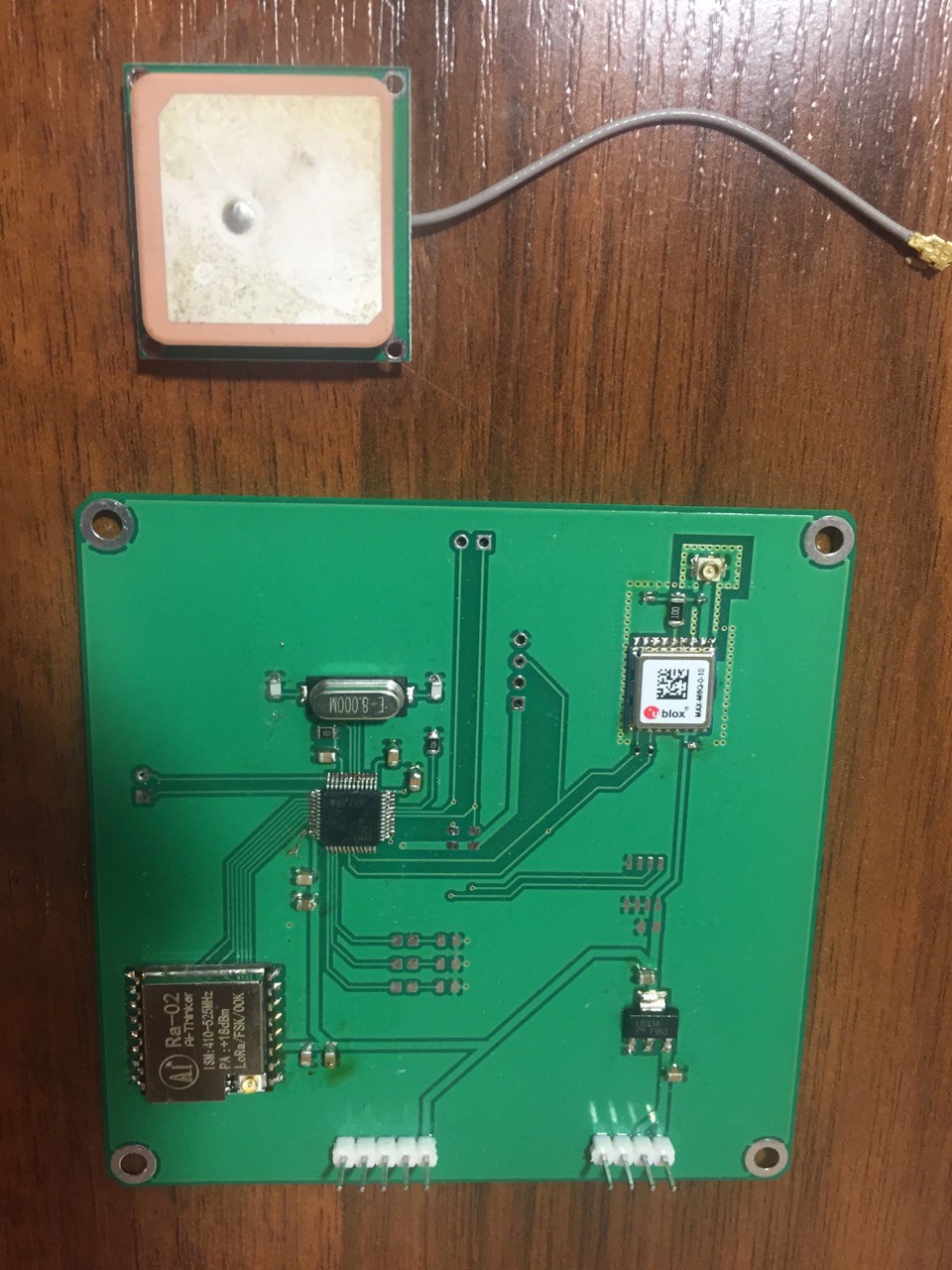
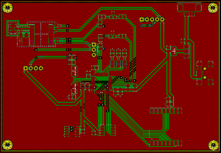
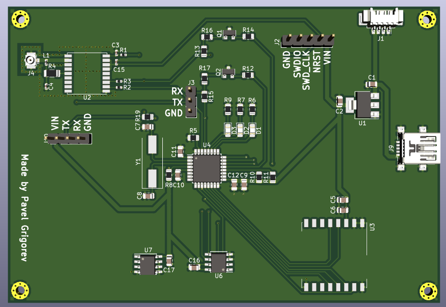
It is a hobby project main goal of which is to build a PCB board that can receive the GPS signal and send its location to the Ground Station
To make the experience fit your profile, pick a username and tell us what interests you.
We found and based on your interests.
IMG_2096.MOVAirborn module works, shows its coordinatesquicktime - 26.78 MB - 01/19/2022 at 10:58 |
|
|
IMG_1956.MOVW25Q128, Temperature sensor and UART checkquicktime - 20.25 MB - 12/06/2021 at 16:18 |
|
|
Airbornmodule.pdfAirborn module Kicad schematicsAdobe Portable Document Format - 125.99 kB - 11/16/2021 at 11:36 |
|
|
FyulzTS5.mp4GPS LoRa STM32 checkMPEG-4 Video - 5.28 MB - 10/30/2021 at 09:40 |
|
due the fact Airborn module will be used in cubesat it has to be in pc104 format.
I had to redesign the PCB. Also, I have simplified the architecture - following one of the most important aerospace rules KISS (keep it simple and stupid).
Btw, Airborn module works very well! the UBLOX module was pretty challenging and it took me nice amount of time to program it and debug it.
In RF design is it very crusual to consider following aspects:
- location
- noise
- microstrip calculation
- soldering quality
- ESD protection
That was pretty interesting and challenging to solder and test all the hardware. At the moment so far everything works flawlessly.
I have a main STM32 microcontroller that controls the boards logic.
I have a temperature sensor that will provide the thermal condition in air
I have Flash memory that records everithing I want :)
And I have LoRa module that sends all that information in protocol array which I didn't made yet =) but module works just fine.
Also those transistor-swiches are working just fine, with these "little guys" I can manage not to send something to GPS by mistake .
For now I have left the Ublox GNSS module, which i think going to be the most challenging. However, let's see! Rock'n'roll!
Now it is time to solder all SMD components on the PCB. It is gonna be superfun with the cool brand new TS100 solder iron :P
here is the board it is 2 layers 108x75mm PCB ready to be ordered
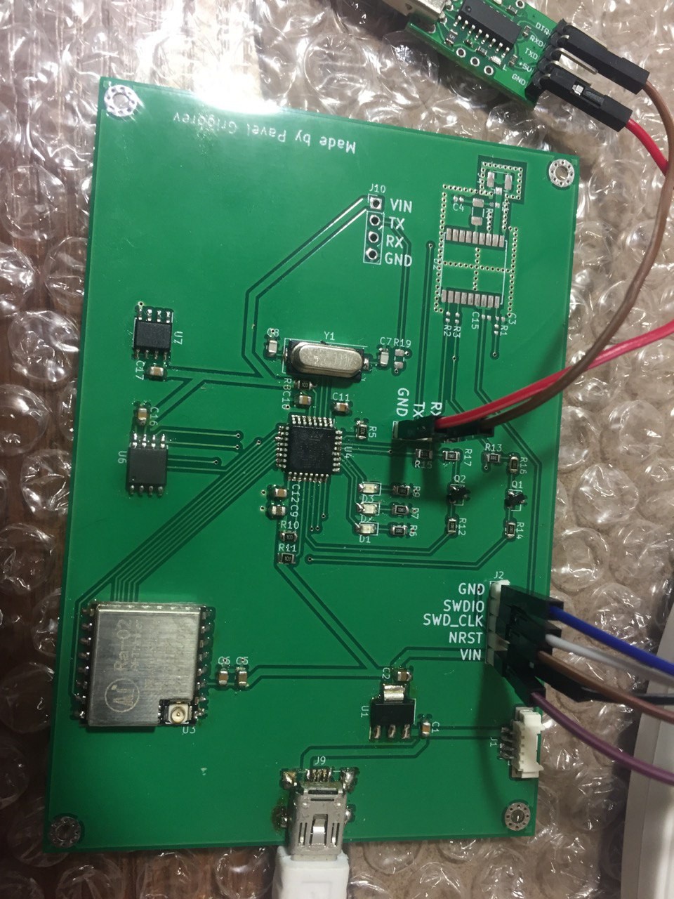
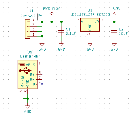
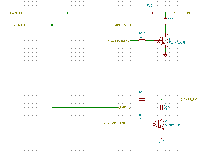
Due the fact that STM32 has only one UART line, here is the way to use microcontroller with 2 UART devices: DEBUGGER and UBLOX
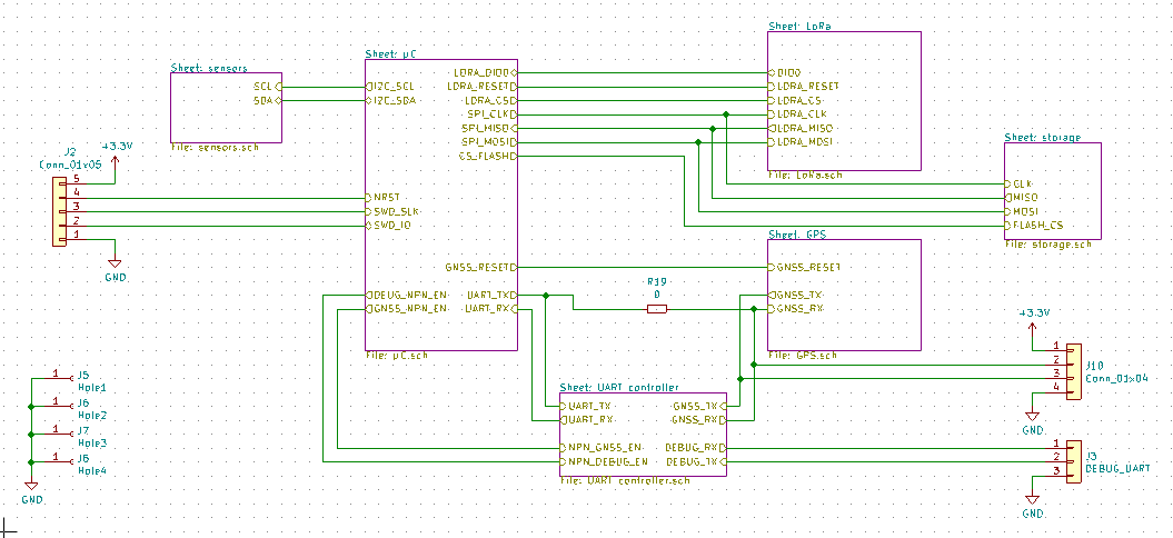
This is the overall schematics view without power input. Here is a GNSS module UBLOX MAX8M that sends location to the µC stm32 the input bytes are stored then in the W25Q flash storage with the temperature bytes getted from the LM75 sensor. After it send via LoRa to the ground station.
Here is the input power part. It consist of 2 parts, the USB mini for easy use and pico blade connector. In the flight power supply will be provided from the molex 1x4 connector through the LD1117* LDO that will convert voltage into 3.3V.
Create an account to leave a comment. Already have an account? Log In.
Become a member to follow this project and never miss any updates
By using our website and services, you expressly agree to the placement of our performance, functionality, and advertising cookies. Learn More