 danjovic
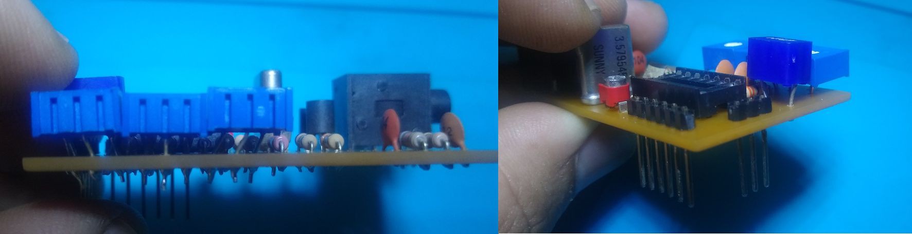
Just finished to assemble the prototype of the A/V board.
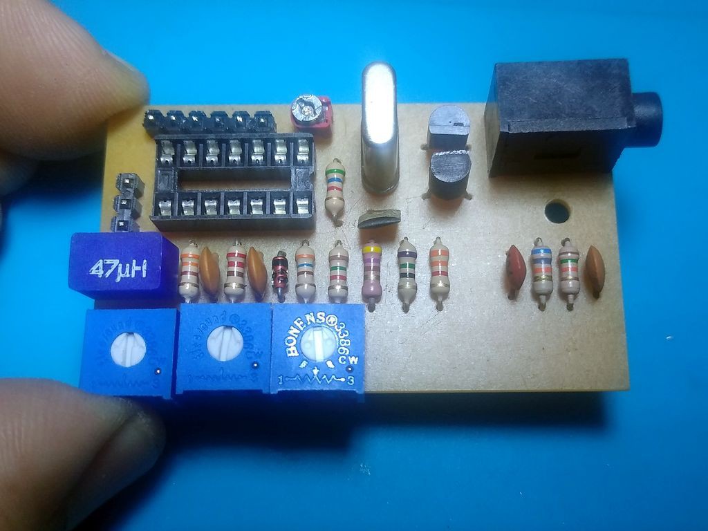
I was able to reuse the trimmer from the original modulator board, but it was necessary to bend the leads of the inductor and the trim-pots
I have already updated the board layout to accommodate the alternate footprints for the trim pot, the inductor and also the trimmer. I should print the board on paper to do a tryout before uploading the sources to github
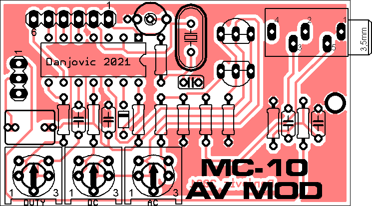
It was not possible to have an alternate jack. I should release 2 more versions for alternate types of 3.5mm jacks.
Discussions
Become a Hackaday.io Member
Create an account to leave a comment. Already have an account? Log In.